I recently bought a 2 device set VL53L0x from STM, and soldered my own Grove connector to it. The shut down signal from the VL53L0x is attached directly to Vdd.
When I connect this setup to the GrovePi (with latest firmware), the GrovePi stops working: I2cDetect does not get a 04 detect anymore and the VL53L0x does not get detected at its standard 29 address. When I use a Switchdoc Labs Pi2Grover, I can detect the 29 address and interact with it. So my connector is soldered correctly and the device is functional, meaning the problem lies with the GrovePi.
What is special about the GrovePi that makes it go non-operational when attaching a non-Grove item to the I2C bus?
(The same with the HDMI to LVDS hub of the PiTopCeed: when that one is attached, the GrovePi is not operational)
Added:
found the paragraph about adding custom sensors. But that probably doesn’t change the fact that the GrovePi+ address of 04 should be visible by I2CDetect when a custom sensor is attached.
Hi there,
By how you’re describing the situation, it seems there’s something on the I2C line that’s happening.
So, the problem has to be hardware-related.
Think of it: if your GrovePi disappears along with your Vl53L0x chip when you connect them, then it means there’s something on the sensors’ board that’s making the I2C line unuseable - I’m drawing this conclusion because with other I2C devices it works.
Also, while I was reading the datasheet of your [VL53L0X] (http://www.st.com/content/ccc/resource/technical/document/datasheet/group3/b2/1e/33/77/c6/92/47/6b/DM00279086/files/DM00279086.pdf/jcr:content/translations/en.DM00279086.pdf) at page 7 (device pin out section), I saw that shutdown pin has to be tied to GND in order to activate it - just a fact here.
I’m suggesting you to draw us a diagram / schematic of your circuit (resistors, power lines, your chip, everything) and from then on give a proper diagnostic.
Here are a couple of tools you can use in order to make a diagram of your circuit:
-
schematic.com - don’t forget to make the “project” public
-
fritzing.org - you have to download it in order to use - it’s very fast
-
Something like Eagle, but I surely don’t recommend that - it’s too complex for what you need
Thank you!
Thx for the reply, Lucian.
But as I said, I can communicate with the device without the Grove2Pi+, using Switchdoc Labs Pi2Grover. So the device does work. It gives me correct distance readings.
The shutdown pin indeed is active LOW, meaning it will SHUT DOWN. To keep it on, it has to be inactive, meaning it has to be tied to Vdd.
There is no schematic to include: SDA is SDA, SCL is SCL, VCC is VDD and GND is GND, while keeping shutdown tied high over the built-in resistor of the satellite board made by STM themselves.
And as I mentioned before, I have a similar problem with the HDMI to LVDS hub of the PiTopCeed. When that one is attached, the GrovePi is also not operational i.e. the 0x04 address disappears.
Hi,
I took a look over the GrovePis schematics and I’ve noticed that for the I2C lines there’s a level converter that translates 5V to 3.3V for the Raspberry Pi, so that might be a problem for you since you’re sensor operates at 3.3V.
It would be great if you can connect your sensor with some jumpers directly to the Raspberry Pi (while being with the GrovePi on top of it) and tell us how it goes.
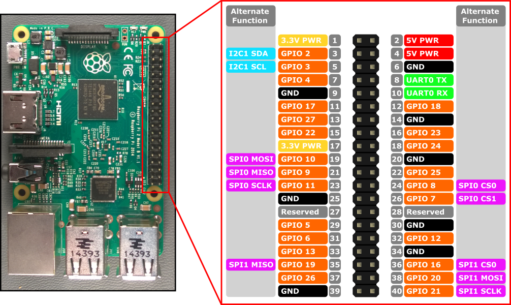
You need to connect your sensor to the following pins on the Raspberry Pi:
-
pin 1 - 3.3 VCC
-
pin 2 - SDA
-
pin 3 - SCL
-
pin 9 - GND
Here’s a pin-out of the RaspberryPi to give you a better idea:
Please, try it out this way and tell if it solved your problem.
We appreciate detailed answers.
Thank you!