Dust Sensor & Barometer Examples

Hi @Shoban,

I want to measure the air pressure at different levels using barometers at one time. So lets say that I want to measure pressure at 4 different levels, then how can I do that? Any suggestion? What is the best way to do it in this case?

For the LED, I changed the polarities and even I used another sensor with another LED but still it did not work.

-Lokesh

Hi @lokesh.pakal90,

The constraint set by the number of i2c addresses for BMP280 Barometer sensor, restricts its use, to a maximum of two on a GrovePi. So what you can do is to use two GrovePi boards and four of BMP280 or BME280 barometer sensors, with two sensors on each GrovePi board.

For the LED bink issue, can you send us a screenshot of what is printed on the terminal when you run grove_led_blink.py.

Please let us know if this helps,
-Shoban

Hi @Shoban,

Do you have any example, where two BMP280 or BME280 barometer sensors are used? Or can you provide me one please? Also I am not able to find the example for BMP280 or BME280 sensor.

I can only see the examples for BMP085 and BMP180 from the link below:

I have not tested the LED blink, I will keep you updated about it as soon as I got the results for it.

-Lokesh

Hi @lokesh.pakal90,

Sorry, we do not have any examples for the BMP280 or the BME280 sensors. I find some python examples for BMP280 here and for BME280 here. I am not sure of how well they would work, you can give them a try if you have the resources. They should work on the I2C pins (SDA and SCL) of the Raspberry Pi or on any I2C port of GrovePi.

Please let us know if this helps,
-Shoban

Hi @Shoban,

Can I use multiple numbers of BMP085 or BMP180 with one Grovepi as a replacement of BMP280 and BME280?

-Lokesh

Hi @lokesh.pakal90,

It wouldn’t be possible to use multiple BMP085 or BMP180 as a substitute for BMP280 or BME280. This is because BMP085 or BMP180 support only one i2c address, hence when you use multiple of these sensors, GrovePi will not be able to distinguish between them. Whereas in case of BMP280 or BME280, you can select the I2C address for the sensor from the two available addresses(0x77 and 0x76).

-Shoban

Hi @Shoban,

Can you please provide me a python example for HP206C barometer sensor with Arduino? I have decided to use Arduino with HP206C barometer sensor for one set-up and GrovePi with HP206C barometer sensor for another set-up. In this way I will have two different set-ups with 2 sensors connected to 2 different hardware. If we run them this way, then do you know how can I run two different python codes at same time for these 2 set-ups?

Lokesh

Hi @Shoban again,

I am running BMP280 with my Grovepi using the example you have given to me earlier. But I am getting a default value. Can you please tell me what is the issue in this case? It detects the I2C port as shown in the picture.

Lokesh

Hi @lokesh.pakal90,

You can find an Arduino example to use HP206 here. But you may have to figure out a way to the send data back to the Pi from the Arduino.

We have an example project in Arduberry here which allows you to upload a sketch on the Arduberry and read it from python.However you will have to update this to make it work with a normal Arduino.

For BMP280, can you post the code can you post the code that you are using.

-Shoban

Hi @Shoban,

I am not aiming to work on arduino at the moment as I have got 3 BMP280 sensors. So if I can use 2 sensors to a GrovePi once, then it will be great. Currently I am using HP206C and BMP280 at a time. I am getting readings from HP206C correctly where I am having problem with BMP280. Each time I run BMP280, I am getting default values as I posted in my previous post.

I am using the example from the link below:

I am running BmpTempCalcTest.py

Lokesh

Hi @lokesh.pakal90,

Sorry that library looks like it isn’t complete yet, can you try the example given here and let us know if it works for you.

Note: You can use only one HP206c with address 0x76 and BMP280 with address 0X77 together on the GrovePi.

-Shoban

Hi @Shoban,

Both of them worked. However the pressure I am getting from one sensor is 1002.45 and the pressure from another sensor is 1004.22. So there is a big difference. Is it because I am using two different sensors?

I removed HP206C and replaced it with another BMP280. So now I am connected with 2 BMP280 sensors with one GrovePi. But when I run i2cdetect -y 1, I can only see one address. That is 0x77. Could you please tell me why I am not able to see 0x76 in this case?

My one BMP280 sensor is working but the other one is not. Here is the screenshot of the output I am getting at the moment.

Hi @lokesh.pakal90,

Can you please test the following and report the results to us:

  • Connect only one BME280 Sensor at a time.
  • Do an i2c detect -y 1 with the BME280 for which you have the code working and with the BME280 for which the code isn’t working.
  • Then connect both the BME280 sensor to GrovePi, make sure one sensor has an address 0x77 and the other has 0x76, by adjusting the address selector on the Sensor board and do an i2c detect -y 1.

If you find that the BME280 sensor code working with the address 0x76 and not working with the address 0x77, then its because the code that you are using BME280.py works for only the address 0x76.
To make it work with 0x77, replace all the 0x76 in the code to 0x77.

Please let us know if this helps,
-Shoban

Hi @Shoban,

Please note I am using BMP280, not BME280.
I did the following,

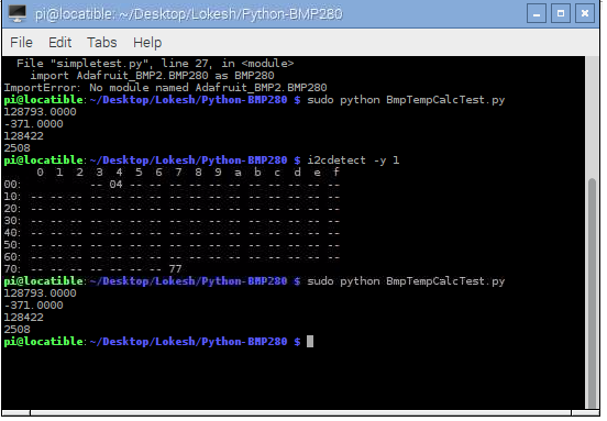
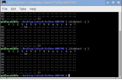
  1. I checked i2cdetect -y 1 command using both the sensors separately. And every time they detect default address 0x77.

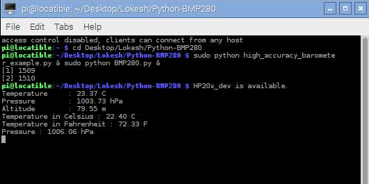
  2. I ran the code you sent to me earlier. Both the sensors work well for 0x77 address.

  3. Then I changed the code for 0x76 address and here is the code I am using at the moment,

Distributed with a free-will license.

Use it any way you want, profit or free, provided it fits in the licenses of its associated works.

BMP280

This code is designed to work with the BMP280_I2CS I2C Mini Module available from ControlEverything.com.

https://www.controleverything.com/content/Barometer?sku=BMP280_I2CSs#tabs-0-product_tabset-2

import smbus
import time

Get I2C bus

bus = smbus.SMBus(1)

BMP280 address, 0x76(118)

Read data back from 0x88(136), 24 bytes

b1 = bus.read_i2c_block_data(0x76, 0x88, 24)

Convert the data

Temp coefficents

dig_T1 = b1[1] * 256 + b1[0]
dig_T2 = b1[3] * 256 + b1[2]
if dig_T2 > 32767 :
dig_T2 -= 65536
dig_T3 = b1[5] * 256 + b1[4]
if dig_T3 > 32767 :
dig_T3 -= 65536

Pressure coefficents

dig_P1 = b1[7] * 256 + b1[6]
dig_P2 = b1[9] * 256 + b1[8]
if dig_P2 > 32767 :
dig_P2 -= 65536
dig_P3 = b1[11] * 256 + b1[10]
if dig_P3 > 32767 :
dig_P3 -= 65536
dig_P4 = b1[13] * 256 + b1[12]
if dig_P4 > 32767 :
dig_P4 -= 65536
dig_P5 = b1[15] * 256 + b1[14]
if dig_P5 > 32767 :
dig_P5 -= 65536
dig_P6 = b1[17] * 256 + b1[16]
if dig_P6 > 32767 :
dig_P6 -= 65536
dig_P7 = b1[19] * 256 + b1[18]
if dig_P7 > 32767 :
dig_P7 -= 65536
dig_P8 = b1[21] * 256 + b1[20]
if dig_P8 > 32767 :
dig_P8 -= 65536
dig_P9 = b1[23] * 256 + b1[22]
if dig_P9 > 32767 :
dig_P9 -= 65536

BMP280 address, 0x76(118)

Select Control measurement register, 0xF4(244)

0x27(39) Pressure and Temperature Oversampling rate = 1

Normal mode

bus.write_byte_data(0x76, 0xF4, 0x27)

BMP280 address, 0x76(118)

Select Configuration register, 0xF5(245)

0xA0(00) Stand_by time = 1000 ms

bus.write_byte_data(0x76, 0xF5, 0xA0)

time.sleep(0.5)

BMP280 address, 0x76(118)

Read data back from 0xF7(247), 8 bytes

Pressure MSB, Pressure LSB, Pressure xLSB, Temperature MSB, Temperature LSB

Temperature xLSB, Humidity MSB, Humidity LSB

data = bus.read_i2c_block_data(0x76, 0xF7, 8)

Convert pressure and temperature data to 19-bits

adc_p = ((data[0] * 65536) + (data[1] * 256) + (data[2] & 0xF0)) / 16
adc_t = ((data[3] * 65536) + (data[4] * 256) + (data[5] & 0xF0)) / 16

Temperature offset calculations

var1 = ((adc_t) / 16384.0 - (dig_T1) / 1024.0) * (dig_T2)
var2 = (((adc_t) / 131072.0 - (dig_T1) / 8192.0) * ((adc_t)/131072.0 - (dig_T1)/8192.0)) * (dig_T3)
t_fine = (var1 + var2)
cTemp = (var1 + var2) / 5120.0
fTemp = cTemp * 1.8 + 32

Pressure offset calculations

var1 = (t_fine / 2.0) - 64000.0
var2 = var1 * var1 * (dig_P6) / 32768.0
var2 = var2 + var1 * (dig_P5) * 2.0
var2 = (var2 / 4.0) + ((dig_P4) * 65536.0)
var1 = ((dig_P3) * var1 * var1 / 524288.0 + ( dig_P2) * var1) / 524288.0
var1 = (1.0 + var1 / 32768.0) * (dig_P1)
p = 1048576.0 - adc_p
p = (p - (var2 / 4096.0)) * 6250.0 / var1
var1 = (dig_P9) * p * p / 2147483648.0
var2 = p * (dig_P8) / 32768.0
pressure = (p + (var1 + var2 + (dig_P7)) / 16.0) / 100

Output data to screen

print “Temperature in Celsius : %.2f C” %cTemp
print “Temperature in Fahrenheit : %.2f F” %fTemp
print "Pressure : %.2f hPa " %pressure

And this is the code for 0x77 address (it is working fine)

Distributed with a free-will license.

Use it any way you want, profit or free, provided it fits in the licenses of its associated works.

BMP280

This code is designed to work with the BMP280_I2CS I2C Mini Module available from ControlEverything.com.

https://www.controleverything.com/content/Barometer?sku=BMP280_I2CSs#tabs-0-product_tabset-2

import smbus
import time

Get I2C bus

bus = smbus.SMBus(1)

BMP280 address, 0x77(118)

Read data back from 0x88(136), 24 bytes

b1 = bus.read_i2c_block_data(0x77, 0x88, 24)

Convert the data

Temp coefficents

dig_T1 = b1[1] * 256 + b1[0]
dig_T2 = b1[3] * 256 + b1[2]
if dig_T2 > 32767 :
dig_T2 -= 65536
dig_T3 = b1[5] * 256 + b1[4]
if dig_T3 > 32767 :
dig_T3 -= 65536

Pressure coefficents

dig_P1 = b1[7] * 256 + b1[6]
dig_P2 = b1[9] * 256 + b1[8]
if dig_P2 > 32767 :
dig_P2 -= 65536
dig_P3 = b1[11] * 256 + b1[10]
if dig_P3 > 32767 :
dig_P3 -= 65536
dig_P4 = b1[13] * 256 + b1[12]
if dig_P4 > 32767 :
dig_P4 -= 65536
dig_P5 = b1[15] * 256 + b1[14]
if dig_P5 > 32767 :
dig_P5 -= 65536
dig_P6 = b1[17] * 256 + b1[16]
if dig_P6 > 32767 :
dig_P6 -= 65536
dig_P7 = b1[19] * 256 + b1[18]
if dig_P7 > 32767 :
dig_P7 -= 65536
dig_P8 = b1[21] * 256 + b1[20]
if dig_P8 > 32767 :
dig_P8 -= 65536
dig_P9 = b1[23] * 256 + b1[22]
if dig_P9 > 32767 :
dig_P9 -= 65536

BMP280 address, 0x77(118)

Select Control measurement register, 0xF4(244)

0x27(39) Pressure and Temperature Oversampling rate = 1

Normal mode

bus.write_byte_data(0x77, 0xF4, 0x27)

BMP280 address, 0x77(118)

Select Configuration register, 0xF5(245)

0xA0(00) Stand_by time = 1000 ms

bus.write_byte_data(0x77, 0xF5, 0xA0)

time.sleep(0.5)

BMP280 address, 0x77(118)

Read data back from 0xF7(247), 8 bytes

Pressure MSB, Pressure LSB, Pressure xLSB, Temperature MSB, Temperature LSB

Temperature xLSB, Humidity MSB, Humidity LSB

data = bus.read_i2c_block_data(0x77, 0xF7, 8)

Convert pressure and temperature data to 19-bits

adc_p = ((data[0] * 65536) + (data[1] * 256) + (data[2] & 0xF0)) / 16
adc_t = ((data[3] * 65536) + (data[4] * 256) + (data[5] & 0xF0)) / 16

Temperature offset calculations

var1 = ((adc_t) / 16384.0 - (dig_T1) / 1024.0) * (dig_T2)
var2 = (((adc_t) / 131072.0 - (dig_T1) / 8192.0) * ((adc_t)/131072.0 - (dig_T1)/8192.0)) * (dig_T3)
t_fine = (var1 + var2)
cTemp = (var1 + var2) / 5120.0
fTemp = cTemp * 1.8 + 32

Pressure offset calculations

var1 = (t_fine / 2.0) - 64000.0
var2 = var1 * var1 * (dig_P6) / 32768.0
var2 = var2 + var1 * (dig_P5) * 2.0
var2 = (var2 / 4.0) + ((dig_P4) * 65536.0)
var1 = ((dig_P3) * var1 * var1 / 524288.0 + ( dig_P2) * var1) / 524288.0
var1 = (1.0 + var1 / 32768.0) * (dig_P1)
p = 1048576.0 - adc_p
p = (p - (var2 / 4096.0)) * 6250.0 / var1
var1 = (dig_P9) * p * p / 2147483648.0
var2 = p * (dig_P8) / 32768.0
pressure = (p + (var1 + var2 + (dig_P7)) / 16.0) / 100

Output data to screen

print “Temperature in Celsius : %.2f C” %cTemp
print “Temperature in Fahrenheit : %.2f F” %fTemp
print "Pressure : %.2f hPa " %pressure

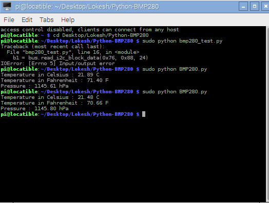
Both the codes are the same. The only difference is that I am using 0x76 address for the first code (which is not working) and 0x77 address for the second code (which is working.)

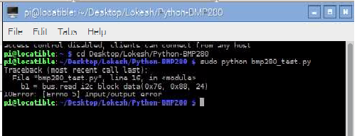
I am getting the error which is in the picture.

Here is the connection picture to the sensor when I am using the code for 0x76 address.

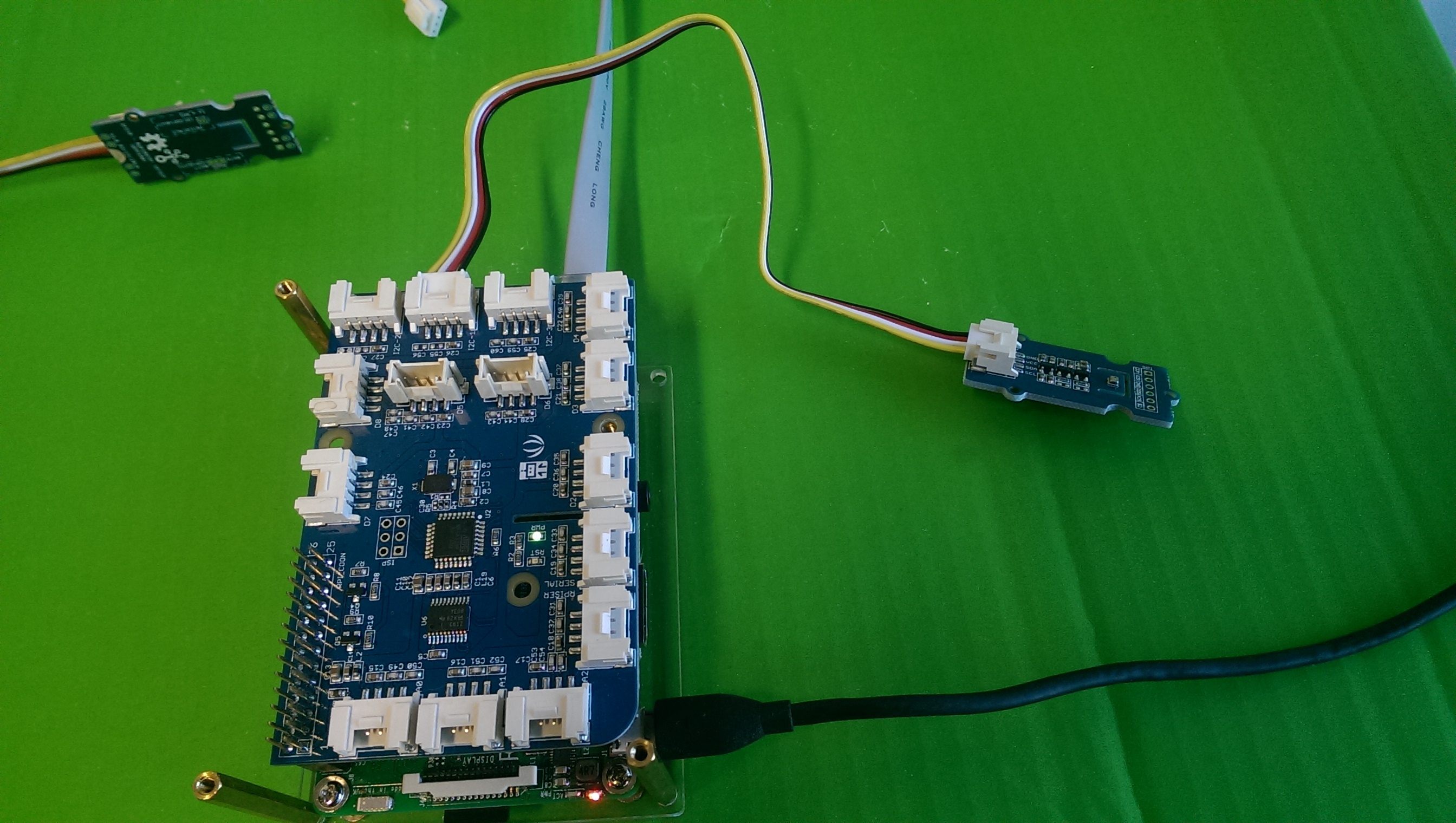
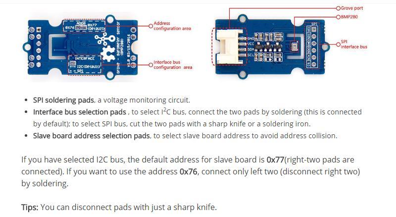
Is there anything wrong in the connection? In the previous post you said that, I have to change the address to 0x76 by adjusting the address selector on the sensor board. How can I do that? Can you please post a picture or something about it?
Thanks.

Lokesh

Hi @lokesh.pakal90,

It looks like the default address of BMP280 sensor is 0x77, thats the reason both the sensor display 0x77 as their I2C address on i2c detect -y 1. You will have to change the address of one of the sensors to 0x76 as explained in the image below

For more details refer to this page.

Please let us know if this helps,
-Shoban

Hi @Shoban,

It seems I have to do soldering if I need to use 2 BMP280 sensors with one GrovePi. However I do not have it at the moment. Could you please help me with the following?

  1. I am using HP206C whose default address is 0x76 and BMP280 whose default address is 0x77. I am running both the sensors at the same time. First set of measurements are from HP206C high-accuracy barometer and the second set of measurements are from BMP280 barometer. Please refer to the picture below for the output. Both the sensors are at the same level and at the same place. Then could you please tell me why there is a difference between outputs? The pressure from HP206C is 1003.73 hPa while the pressure obtained from BMP280 is 1006.06 hPa. There is a difference of around 2.5 hPa in the measurements. Why there is a difference in this case? I was expecting that both the sensors would give almost similar measurements.

  2. I am also aiming to run seeeduino with BMP280. Do you have any python example in this case?

-Lokesh

Hi @lokesh.pakal90,

From datasheets of HP206 and BMP280 sensors it can be seen that the difference in values is because of the accuracy difference between the two sensors. The HP206C has an absolute accuracy of ±3hPa and BMP280 has an absolute accuracy of ±1hPa. So it is possible to have a difference of 2.5hPa in between them.

You can refer here for the datasheets of HP206 and BMP280.

Sorry we have not used seeeduino before and we do not have any support for it. However if you can refer to this post to get an idea as to how to read values from arduino using python.

Please let us know if this helps,
-Shoban

I am trying to confirm that the values I receive from the High Accuracy Barometer sensor are accurate.
I am using this sensor: http://wiki.seeed.cc/Grove-Barometer-High-Accuracy/
I am running the high_accuracy_barometer_example.py program with the following output:
Temperature: 21.77 C
Pressure: 964.09 hPa
Altitude: 417.48 m
The temperature and Altitude seem correct.
For the pressure of 964 hPa, I want to convert it to what the weather stations use to verify the accuracy.
When I use a conversion found online, I get this: 964 hPa = 13.992370709785 psi
However typical pressure is 29 to 31 as reported by the weather.
So is my conversion correct or is the sensor giving out inaccurate data?
Thanks so much for your help!

Hi @linda1,

It looks like the values you get from the Barometer sensor are correct. The conversion too looks correct but I would like you to double check if your reference pressure is in “PSI” units. It appears to be in “Hg”. Refer to this webpage for their relationship. The range you have mentioned(29 to 31) correlates with the values you get provided the reference pressure you are comparing it with is in “Hg”.

Please let us know if this helps,
-Shoban