Note that the instructions for the line follower presented there are for the “old” (red) line follower board with plastic spacers and an acrylic “foot” to protect the sensor bar.
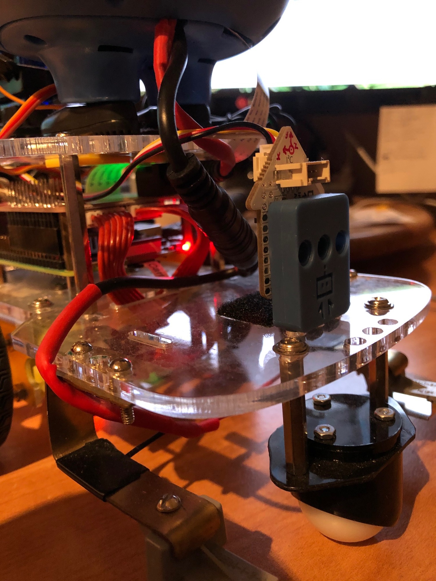
The new sensor kit, (black), has four metal screws - all the same length - four metal washers, two extension posts along with the line follower board and cable.
How should the screws, washers, posts (etc.) be assembled?
Given that I already have a distance sensor installed in the “first” i2c slot, (next to Servo 1), and that I also plan to install the Dexter IMU on this 'bot, what is the best way to hook all of these things up so that they present the fewest conflicts, lowest latency, and the best performance.
That is, which devices should be connected to which i2c port(s)?
When you navigate to that page, you (briefly) see the content on that page, which is then immediately covered with a “Are you looking for the GoPiGo-3?” pop-up.
If you click on the “Are you looking for instructions for the GoPiGo3?” link, it brings you back to the original page located at: https://www.dexterindustries.com/gopigo3-tutorials-documentation/*
(See item 1 above.)
. . . and we start the same cycle all over again.
While looking for information on the Dexter IMU, I ran across the documentation for the “black board” version of the Line Follower.
Viz.:
(Shaking head) - I’m still trying to find out about hooking up the IMU on the GoPiGo, but at least I found out where the documentation for the line follower - (that should be linked to the link on the GoPiGo3 page), and figured out how to correctly assemble it. Actually, I guessed and I guessed correctly. I just hate guessing when it comes to electronics.
Why on earth would ANYONE want to bit-bang i2c? That makes about as much sense as using a Bunsen burner to ignite the fuel in a full-bore Hemi. . . .
BTW, The original “Otto” 4-cycle engines did use a Bunsen burner to ignite the fuel, but they maxed out at a mind-boggling 50-60 rpm.
Here you can actually see the guy using a butane lighter to light the burner’s flame on the inlet port where the fuel was ignited.
OK, in your case I understand it - you bought some strange IMU board out of the trunk of someone’s car, instead of the True and Authorized Dexter branded IMU and now you have to pay the price. (Just kidding! I did the same thing with several Vellman RTC modules - cheaper than Adafruit’s by about half - but they only support serial data, not i2c - rats! - I’ll probably find a use for them somewhere.)
Seriously, the Dexter IMU has i2c all over it - why does it have to be bit-banged? I was counting on using an i2c port because I was planning to use the A/D ports for impact “bumpers” around Charlie’s perimeter - I’m already using part of A/D-1 for Charlie’s front bumper!
Rats! Another perfectly good idea down the trash!! (Not really, I’m sure I’ll figure out something - maybe a SparkFun i2c sensor breakout for the bumpers?)
Easy to move to AD-2A and you can later share with AD-2B if you need a second A2D (just not simultaneously, but since there is only one processor it isn’t likely to need two A2D simultaneously, right?)
But the IMU will work fine on AD2, you just have to remember to add port=“AD2” to the init.
Then I surely don’t remember something correctly about the IMU and i2c ports on another post - I thought you had purchased a different manufacturer, (and I was trying to playfully yank your chain about it.)
Guess I’m just being confused.
While we’re on that subject, is there any documentation on exactly how to implement the IMU and make it do useful work - aside from attaching it to the chassis.
DI put together two IMU “projects”, one the balance-bot, and second a “compass bot”. Balance-bot is interesting but not useful for our GoPiGo3 configuration. Compass bot is very well documented:
with pictures and instructions. Compass bot walks you through calibration, and then allows keyboard arrow commands for North, South, East, and West. The program is actually quite sophisticated (more so than absolutely needed) implementing separate multi-tasking for motor commands, sensor reading, and keyboard commands.
The other program that DI put together IMUSensor.py just prints out readings using the InertialMeasurementUnit() class which does not implement the desired mutex protection of the EasyIMUSensor() class. Problem with the EasyIMUSensor() class is that it does not implement “safe” versions to read gyros or read accelerometers. The EasyIMUSensor() needs to be expanded, and I am quite a bit down that path but not finished yet.
By “make it do useful work”, I meant provide the methods for making it do something useful. (i.e. how do I determine my basic “orientation”, (upright, flat on my face, etc.), Am I moving? In what way? etc.)
I don’t expect them to do all the work, but it would be nice to know how to get data into and out of the beastie. Maybe a hint or two on what to do with the data once you use your pliers and wiggle it out would be nice too. Something other than “if bit 17 in the third octet of the sixth LONG value is “zero”, you’ve fallen on your face.” (Datasheet bitmaps can be “interesting” to say the least.)
It goes onto the AD port, which acts as a second bus I2C connector, so it’s completely I2C.
The reason is that there’s a hardware issue with I2C clock stretching on the Pi, so we implemented a different solution.
Very interesting architecture line of thought that I admit I am not knowledgable enough to know to answer correctly. My software architecture may be a set of convenient but poor choices that do not actually offer the protection the mutex is designed to ensure.
Some of Carl’s Python programs instantiate multiple threads. I have not enforced that sensor access via I2C would only be through one thread. I believe in this case the mutex is effective as intended.
Sometimes, Carl is running multiple Python programs, that each instantiate the EasyGoPiGo3 class, and an I2C distance sensor object using HW I2C. (With SW I2C the programs quickly collide causing unrecoverable I2C bus errors that require a reboot to clear.) I do not know if the mutex is totally effective between separate process instances of the EasyGoPiGo3 class, but I2C errors are very, very rare - perhaps once every few months, versus once every hour with SW I2C. I have found that one program’s EasyGoPiGo3 instance configuration (speed) will change another program’s behavior, perhaps because the parameter gets pushed down to the GoPiGo3 controller’s state, but I don’t believe the other Python object instance values are altered. (Found the test_distance_sensor.py and _2.py pair and test_heavy_mutex.py and test_heavy_mutex_2.py that show the mutex is effective between processes - cool.) Wrote a test to prove EasyGoPiGo3 instances do not share/alter vars.
Currently, I am beginning to test a mixed I2C configuration which has one Python program that accesses the ToF Distance Sensor using hardware-HW I2C, and one Python program that accesses the DI IMU via Software-SW I2C via AD1. (The IMU absolutely must be interfaced by software I2C which correctly implements clock stretching, AND seems to allow software error recovery.) I believe I have seen an increase in unrecoverable HW I2C errors, and do not leave Carl alone with the IMU running, for fear I will get up the next morning to find him powered down because he could not use the Distance Sensor to get back on his dock.
Perhaps to get the best benefit of the mutex, I will have to pull all I2C accesses into a single process, and use some form of multi-process messaging to provide sensor data to everyone. That complexity awaits integration. I have a lot of little “test this” and “test that” programs which I want to run without the need to integrate with Carl’s 24/7 “juicer” program that keeps him alive.
Sorry for the wordy answer, and sorry I have hijacked this well intentioned Line-Follower Doc thread.
Apparently, a cost saving decision with nearly endless debate / postings on rasberrypi.org and raspbian.org, that may have been fixed in the RPi4 since I have seen postings both: “it was not”, and “it may be”.
The RPi is very flexible about the GPIO pins, but the built-in I2C only implemented half of the I2C stretch capability that was easy. DI implemented the full I2C stretch on the software I2C sufficient to interface reasonably reliably with the IMU, but my testing (and anecdotal reports from GrovePi3 users) have shown the software I2C to suffer from weekly to monthly unrecoverable failures, where the harware I2C which fails miserably all the time to the IMU, ends up being nearly rock solid with sensors that do not need stretch.
Either someone totally revamps the software solution or someone creates a hardware controller interface that fully implements clock stretching. This would be fun to do, but I’d rather look for a ready-made solution first.
This isn’t the first time either. I recently read an article on how the Pi-4 designers totally borked the USB-C connector power interface by omitting a resistor, or something like that.