I got pivotPi for a grovePi project because I needed a servo. The project is not mobile, so a wall power is sufficient. GrovePi is connected to power through raspberry Pi which is connected to wall power with a power adapter. I would prefer not to have to change or recharge batteries for PivotPi. I would like to onnect PivotPi to a wall power independently, or better yet somehow share power with raspberry Pi’s power.
Does anyone know what options I have?
Thanks!
Roman
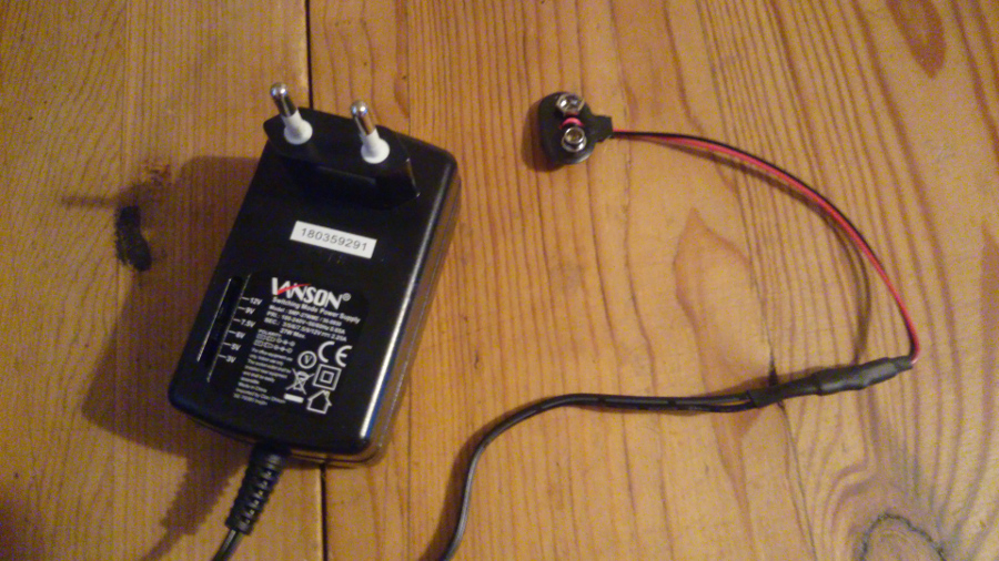
I’m hopefully going to solve this for myself today by solder this to this.
The motive behind this solution is that I’m not sure about what exact 2-pin connector PivotPi uses - and this way I don’t need to bother, I just use the original cord.
I’m of course always open to better / more flexible solutions.
Servos are very “noisy” on the power supply. Keeping the RPi and servo power separate is highly recommended.
Most servos are designed to run on a 6v power supply, but will work (with reduced speed and torque) at voltages as low as 3v or so.
The current requirements of a servo will depend on the model. Some small servos might have a stall current of 500ma at 6v, while larger servos might have a stall current of 3A at 6v.
If you use a wall power supply to power the servos, it would be advised to use one rated for the stall current of all servos you intend to use. For example, if you are using two servos, with stall currents of 750ma and 1500ma, you should use a power supply rated for at least 2250ma (2.25A) continuous. To prevent brown-out or overcurrent conditions, it would be good to oversize the power supply by at least 20%. In the example above, a power supply rated for 2.7A or greater would be ideal.
Make sure you use a regulated power supply. A transformer with a DC output rated for 6v 2A might have a no-load voltage of 9v (too high for servos), and a 2A voltage of only 4.8v (reduced speed and torque). A regulated power supply should have a constant voltage of 6v, whether at no load or at max load.
Hello, Matt! That’s a lot of interesting information!
About regulated power supply: Got a hard time figuring out if the one I got is regulated or not, but I guess it’s not because it says it’s a “switching power supply” - doesn’t sound that regulated. But, I obviously got much to learn about this. Though I plan to get it’s input power from a UPS, and i hope that will help with a pretty clean power flow.
A switching power supply is regulated, so it should be good. You could measure the no-load voltage just to confirm, but typically only the old transformer power supplies are unregulated.
Ok, I did what I tried to explain earlier. frustrating enough, I got my PivotPi/Robot on a remote location(which is the main reason why I need a different power solution than batteries), so I have not been able to test if it works as desired. But hopefully tomorrow.
And I actually found a adapter that declares it’s regulated - and at half the price of the one I bought earlier. Feels good.
Just a word of warning; usually the colors on a snap battery cable (as pictured) apply when connecting to a battery (or battery pack), and would need to be reversed when the cable is used as a power supply. Make sure you double and even triple check the polarity before you connect to the PivotPi.
On a battery (or battery pack), the small snap connector is + and the large snap connector is -. On the mating cable, the large connector would connect to the battery small connector (+), and the small connector would connect to the battery large connector (-).
Using the snap cable as the power source (“simulating” a battery), the small connector should be + (probably the black wire), and the large connector should be - (probably the red wire).
Again, please confirm the polarity before you connect it.
Yes, indeed. I thought I wrote about that, but I must have missed to update my post correctly. I found that a bit confusing at first, but as you wrote, the snap connector coming from the adapter is simulating the battery; which makes it pretty logical. But still, if something could go wrong - this is it.
I’ve double and triple check the output. Should be fine.