I have to disagree about “you can’t stack SPI devices” and “SPI does not support addressing”.
On my Arduino Dues (ARM Cortex M3) I always had several SPI devices simultaneously (e.g., a TFT, a SD card, a couple of arbitrary MCP devices (23S17, 4922, 2304). Of course having proprietary CS/SS ID pins was crucial, but IMO that is part of SPI bus and driver specs, and it is as self-evident like having proprietary device addresses for i2c, and optional address matching on certain devices (like by the SAMD21 = ARM Cortex M0) makes it even more versatile.
And again, Shane, you still are missing the async simultaneous transmission mode for SPI vs. i2c.
But using just SPI for the BP3s provides another priceless valuable feature:
still i2c-1 and i2c-0 stay untouched, so thea are still available for more additional industry standard devices, like ADC, DAC, I/O muxers, MCUs, TFTs, IMUs, US sensors, 74×595 shift ICs, and what ever, without interfering and perhaps blocking the BP3 devices.
PS,
Unfortunately I didn’t get a Voice HAT any more when I tried, but basically a design to make Raspi HATs and shields stackable and provide compatibility to either ones is indispensible for robotic applications.
It was a case of me asking so that I learn the differences. Advantages to disadvantages
The reason that I ask is it seems on many forums people have trouble with stacking SPI devices and there is generally less problems with stacking I2C devices useless there is a conflicting address and this can be fixed easily with a $2 multiplexer.
I generally haven’t run into problem with not enough speed with coms. Only twice, first time was with the BrickPi+ there was a slight bottle neck but it worked by the controls ran on threads on the RPi (counting encoders, PID rountines) so the RPi had to do a lot of R/W to the BrickPi+ but with the BrickPi3 all this code runs on the BrickPi3 and there is only commands sent from the RPi to the BrickPi3. The only time I really hit a wall with I/O was to the camera because it is such large amounts of data 3 bytes per pixel and a large number of pixel and I limited out at 50 frames per second
this discussion is now running way off-topic -
perhaps the site admins can split this topic into 2?
i2c muxers for i2c devices are way no option, because they divide the i2c transmission capacity by the number of attached devices.
e.g., if you have 8 i2c devices on an i2c muxer (e.g., an PCA9548A) then each device can be polled just by less than 1/8 of the basic main bus speed which may last perhaps up to 100ms (for 8 US sensors even way longer), and during polling this 8x muxer then the i2c bus is blocked and the rest of the parallel hooked-up devices (MCPs, PCFs,…) will have to wait until they are on the turn - precious data will be dropped (e.g. encoder readings or i2c soft-pwm generation) and the whole system will be stalling.
OMG, no, stay off of my cloud with stuff like that!
I appreciate very much that Dexter chose SPI for controlling the BP3 shields!
But compatibility must be provided by switchable proprietary CS/SS and additional control pins and a reasonable SPI clock speed (e.g., 2 MHz).
In case of need the shield’s SPI data transmission can be clocked down or slowed down internally by sort of a bitbus protocol.
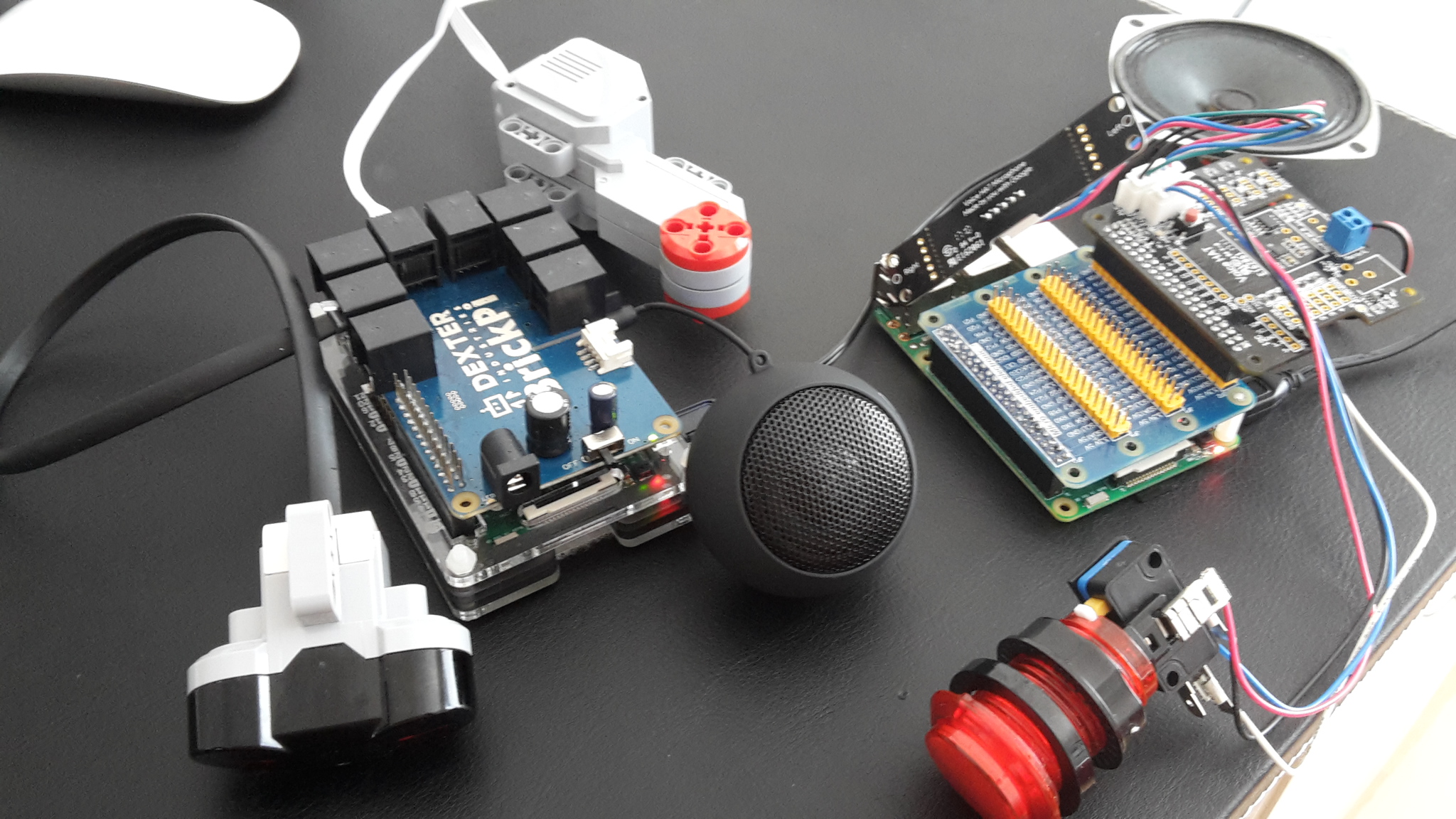
Well, I didn’t understand a word of most of these replies but got around my problem by splitting the tasks between two Raspberry Pis. I have one running Google Voice, which gives instructions to a second attached to the BrickPi3. I am using SSH to communicate between the two.
My voice controlled, motorised personal assistant is a step closer to becoming reality… As you see, I won’t be winning any design prizes just yet…
Hey,
Been working on this for a while. Firstly, using Alexa, then PocketSphinx and now Google Voice. I have a PiStorms module but find it a bit clunky. Looking forward to getting to grips with the BrickPi3. Looks great
Should be able to have the Google Voice Pi near to me - to press the button for activation (I find Alexa’s continuous listening a but unnerving) - and then give instructions to the motorised assistant over SSH. #Nerdvana
Hi Matt,
Thank you for your reply.
I have a working prototype now with the Google Voice Raspberry Pi using voice controls to run the BrickPi3. I attached a Raspberry Pi camera to the robot (which sends video to my Mac) and can now give voice commands to navigate the robot remotely around the other rooms in my apartment.
Another question for you: I have bought a Grove Temperature and Humidity Sensor Pro and have hooked it up to the Grove i2c port. However, I don’t see any instructions in the documentation for the BrickPi3 on how to get Grove sensors to work.
I did see a post that redirected to the GrovePi GitHub python programs, but I am not sure about how to get them to work in the BrickPi3. Do you have any ideas, please?
Many thanks,
Stuart
p.s. I’ll post pictures and ideas for my Google Voice - BrickPi3 setup soon
The Grove port on the BrickPi3 is I2C only, and unfortunately the DHT sensor uses a proprietary protocol. The BrickPi3 Grove I2C port is connected to the Raspberry Pi I2C bus through a voltage level translator. You should be able to use any Grove I2C device, but you will need whatever necessary drivers for the RPi. As an example, the Dexter Industries PivotPi works with the BrickPi3 Grove I2C port, and there are even drivers already available for the RPi (see here).
To use the DHT sensor with the Raspberry Pi, you should use the GrovePi.
if you took C for programming, you might also use i2c-0 on the Pi. I did it already very succesfuuly (not sure if it’s also possible by Python as well).
I would be interest in if people can get i2c-0 to work on the latest models of RPi if I run the command i2cdetect -y 0 it comes up with an error. Apparent on RPi3 and RPi zero this other bus is locked for some RPi hardware, some say for the Blue tooth WiFi
I was reading on another forum that they changed I2C-0 on the RPi3 and Zero W as some hardware on the board is using it (the Blue tooth and Wifi was mentioned).
I might see if I can find some more info on it just to make sure it is still fine to use on current models and if so I will add that line to the config.txt and see if it will work.
as already stated, I am not sure about the zero or the 3 - but why not just try it acc to my guide?
Anyway, as i2c-0 is indispensible for the HATs, it still must exist in some respect:
so If it works it’s fine then,
and if not you at least will have the ultimate answer, eventually
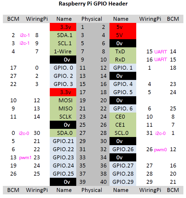
I added the line to the config.txt then when I ran i2cdetect -y 0 it now came up with the with the register. But when I connected my device SDA to pin 27 and SCL to pin 28 then ran i2cdetect -y 0 again it did detect my device but if I plug the same device into pins 3,5 and run i2cdectect -y 1 then it does detect them.
yes, physical pins 27+28 are i2c-0 and physical pins 3+5 are i2c-1.
IIUYC this is also exactly what you found by yourself, didn’t you?
when I connected my device SDA to pin 27 and SCL to pin 28 then ran i2cdetect -y 0 again it did detect my device
But if
ls -l /dev/i2c*
finds i2c-0, then it is actually available.
So in case you failed, check the correct pullups and check SDA, SCL, and GND wiring!
(IIRC, i2c-1 has pre-built-in pullups, i2c-0 not, but for the Pi3 you better ask in the Raspi forums!)
 but got around my problem by splitting the tasks between two Raspberry Pis. I have one running Google Voice, which gives instructions to a second attached to the BrickPi3. I am using SSH to communicate between the two.