The second try:
This build I am using 1mm thick fiber washers everywhere.
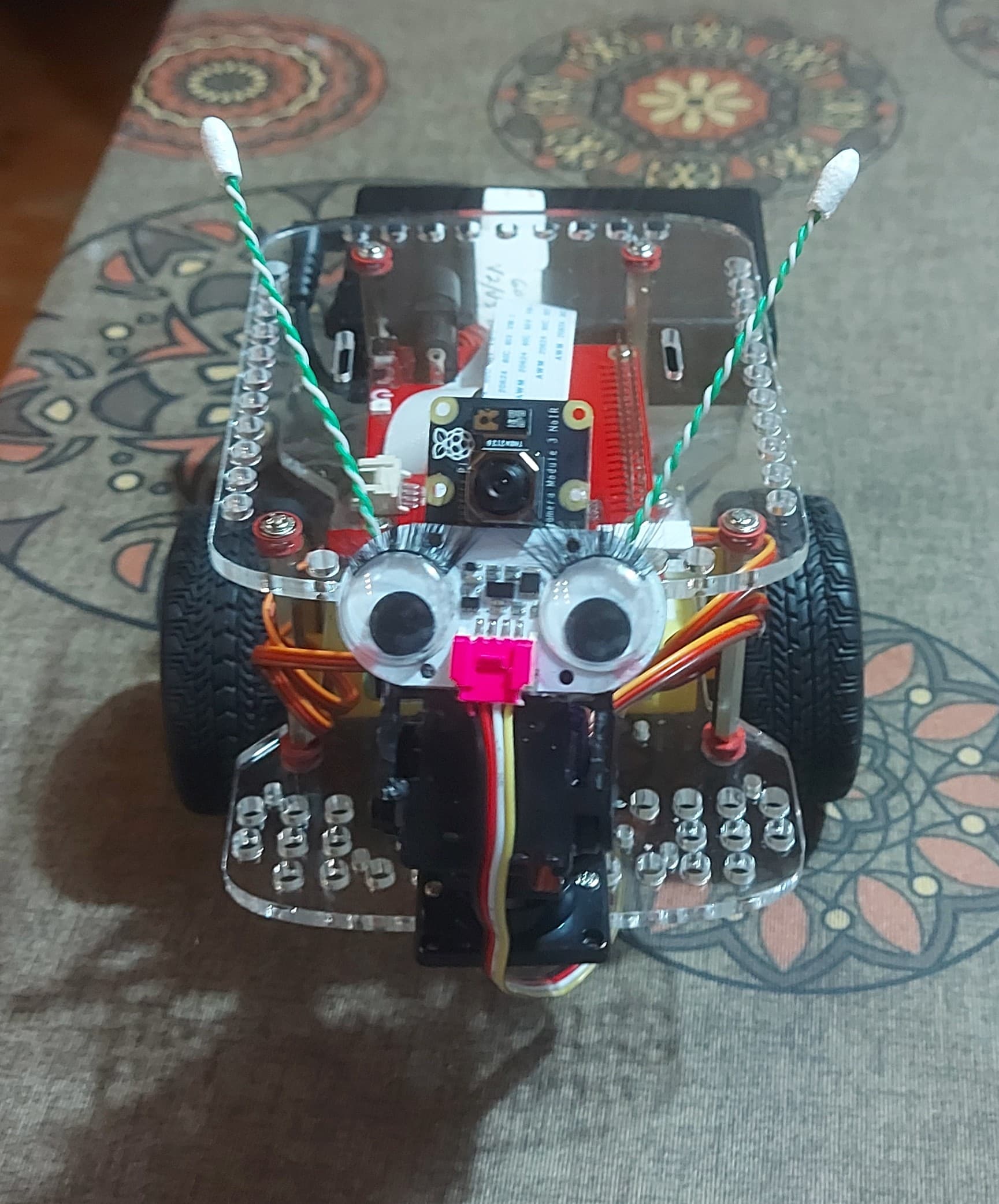
Oh - eye lashes… Adorable.
Very creative.
Charline is looking good.
/K
Well. . . .
Every time I’ve seen two identical characters that are supposed to be opposite genders, the difference is usually red lips and eyelashes.
Since it’s kinda hard to give Charline lips, I was stuck with eyelashes. . .
Hmmm. . . . Lips? Let’s see. . . .
I could paint her Grove connector red, 'eh?
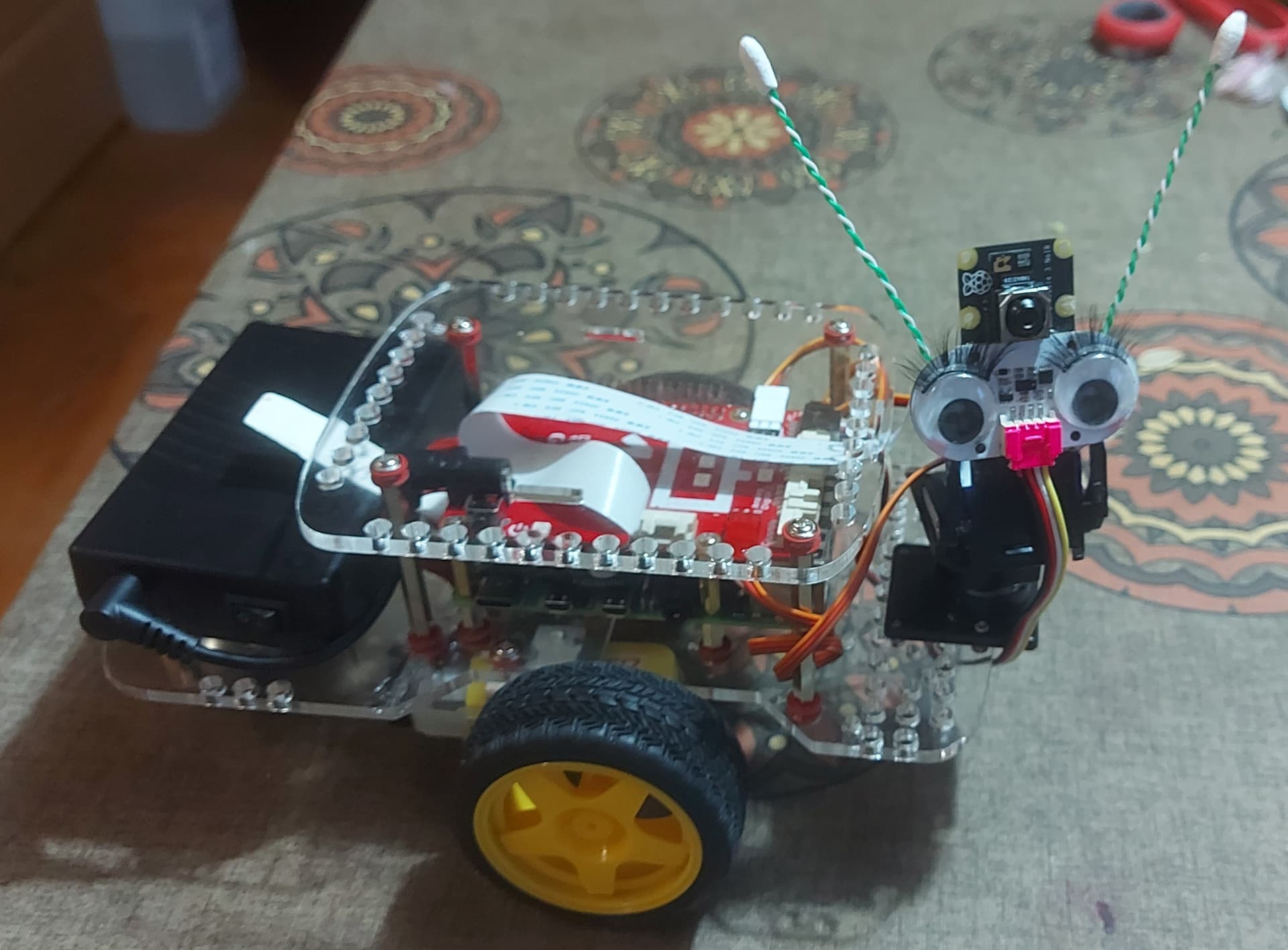
I am planning to give her pink antennae though.
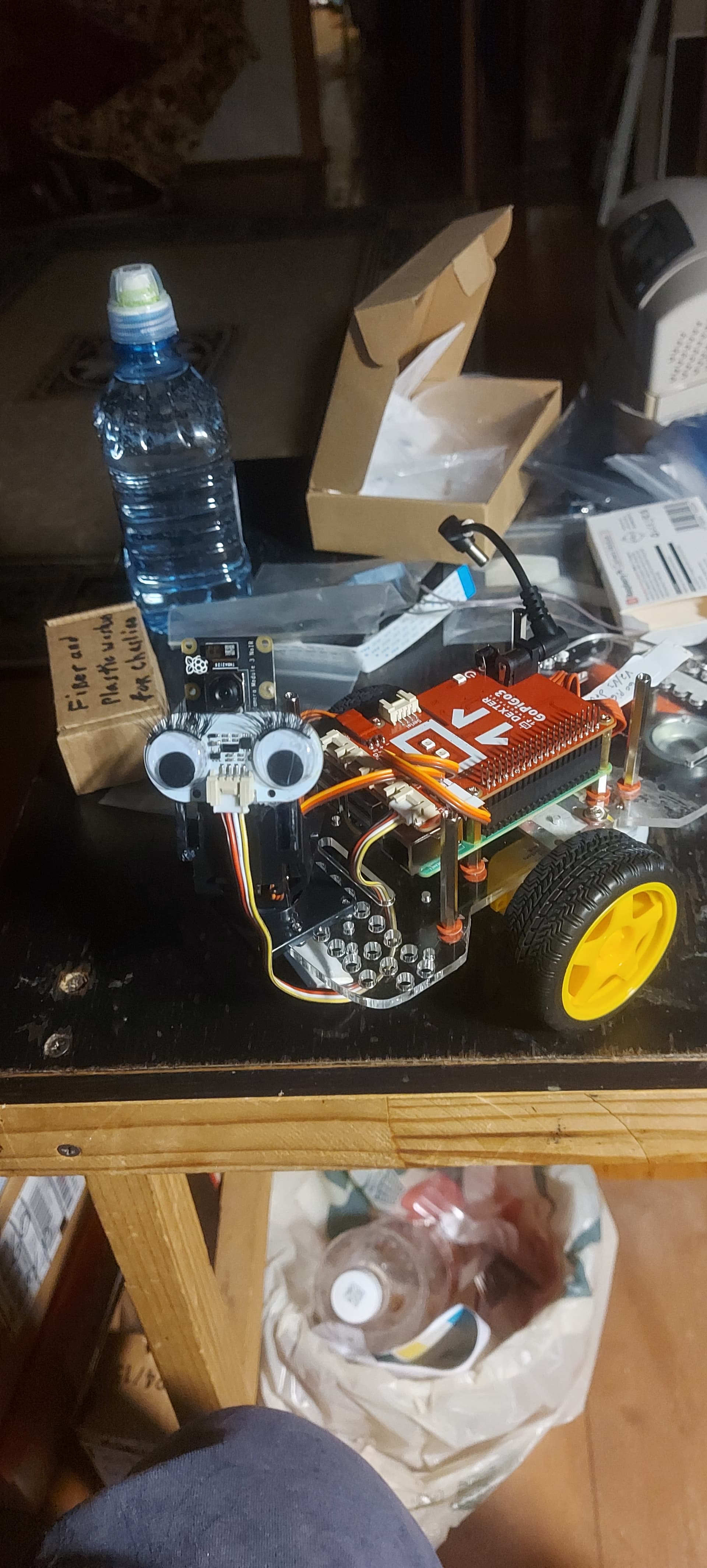
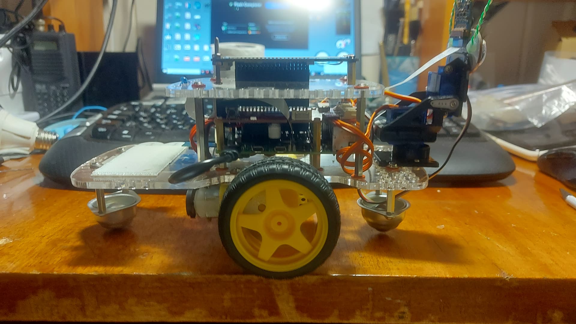
Built using the new V3 camera, an 8-gig Pi-4, and a newer rev controller board.
Done:
Basic build with the camera and the pan-and-tilt installed.
Photo-shoot for all the major fashion magazines.
Basic “Am I alive?” functional testing.
(i.e. It powers up, the servos seek to home position, the “bitness” eye LED’s are the correct color, and it shows as a networked, (as opposed to an access point), network connection.
Todo:
More extensive testing using the GoPiGo O/S.
GoPiGo calibration.
Enable development access.
Test with my joystick enabled FPV robot code.
Install a front bumper.
Build and install an automatic on/off circuit for the supplemental 5v supply.
Retrofit Charline’s battery with replacement 510Ω calibration resistors for the power meter.
Longer range goals:
Integrated status display like Charlie.
(Possibly a touch-enabled OLED?)
Test with my Pi-5.
Test with my Jetson Nano.
Important note:
So far, (knock wood!), with the fiber washers installed, there have been no cracks in the acrylic despite the fasteners being torqued tight.
I have also been updating Charlie to use fiber washers on an ongoing basis. (If I take something apart that can use fiber washers, I install them before reassembly.)
P.S.
I thought that the “lipstick” was a nice touch, though I’m thinking of using a more subdued color in the future as it seems a bit garish. Did you notice the “rosy cheeks”? ![]()
Finding that particular shade of pink was a godsend since I thought I was going to have to mix it myself! It took several tries before I got the amount, its position, and the shape of the “rosy cheeks” right.
P.P.S.
It turns out that I couldn’t find “pink” wire like I needed, so I used the green and green striped wires from a piece of network cable instead . That works since Charlie’s antennae are green network cable wires.
Looks great. I look forward to reports on how well she runs. I hope GoPiGo O/S is up to the challenge.
/K
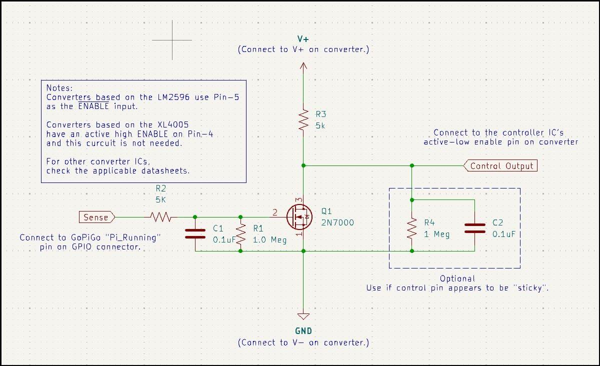
For those who are interested, here is the schematic of the supplemental power control circuit.
Notes:
V+ should be no greater than 60v
Sense should go higher than 2.5v.
The input to the FET contains a 5KΩ current isolation circuit and a passive noise filter for the SENSE input.
The optional circuit on the output, (CONTROL), is to eliminate output “stickiness” due to extremely high impedance inputs.
Buck converters based on the 4005 chip have an active HIGH enable pin on pin-4 so this circuit won’t be necessary. I noticed that the time constant of the input is a bit high on that chip so I added the filtering circuit to it.
Buck converters based on the XL2596 have the active LOW enable pin on pin-5.
The enable pins are tied to either ground, (LM2596), or +V, (XL4005), so they will have to be carefully lifted from their circuit pads before use.
Implementation:
Errata:
On the 4005 buck converter used on Charlie I included the entire input current isolation and filter circuit to the enable pin on the 4005. This provides both a “grid-leak” to prevent charge accumulation and input filtering.
Note that the maximum input voltage to the SENSE pin should be no greater than the applied V+ voltage.
Also note that the enable inputs to the respective buck-converter chips are high impedance inputs, (MOS gate inputs), and the absolute maximum rated leakage current is rated at something like 10μA up to a maximum of V+, output loading of the Raspberry Pi shouldn’t be an issue. However, as a design best-practice, and since the Raspberry Pi’s GPIO pins are limited to an absolute, drop-dead maximum current of 30 miliamps (±, later models might withstand 50μA), the 5k isolation resistance is highly recommended to prevent any circuit failure or defect from burning out the associated pin.
Update:
Charline has shown a nasty tendency to face-plant on any kind of reasonably rapid stop, especially if there’s no battery weight on the rear shelf.
Charlie avoids this tendency by using his line-follower as a front stop. It might be hard on the line-follower, but it keeps him upright.
The solution? A front caster for Charline.
It’s interesting to note that the caster hole spacing in the back and the line-follower hole spacing in the front are the same. So a spare caster fit like a glove!
Additionally, I am working on various display updates so that the robots can communicate necessary information to me, sans sounds that would annoy others.
Aside from the Waveshare 2.13" e-ink display on Charlie, I have
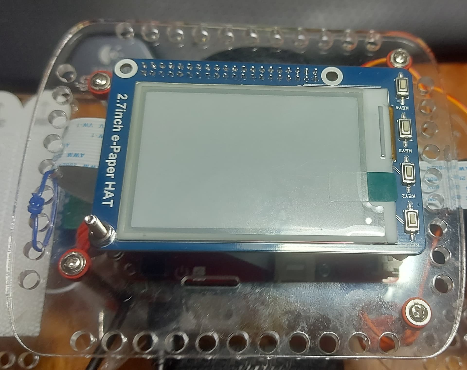
a Waveshare 2.7" e-ink display,
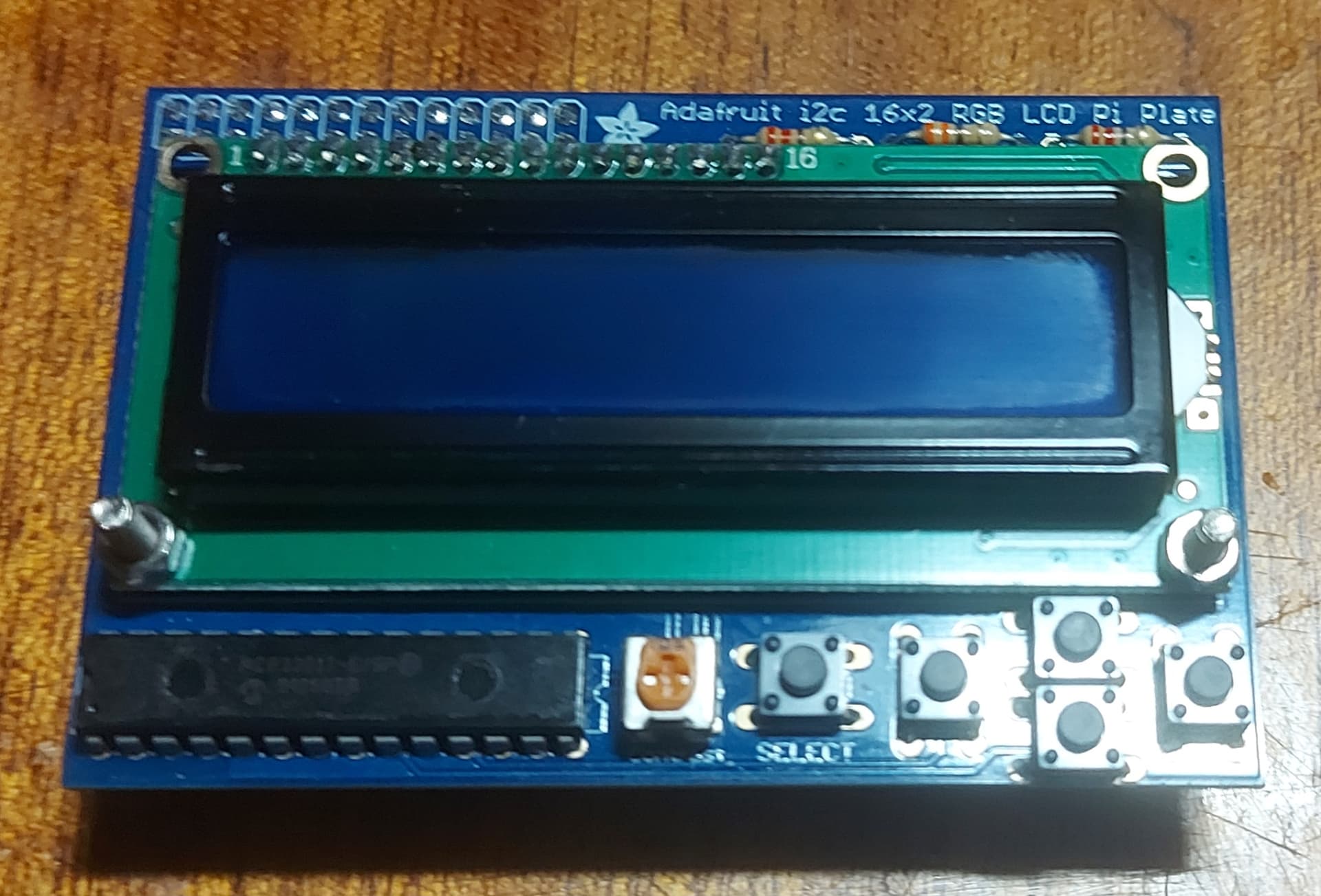
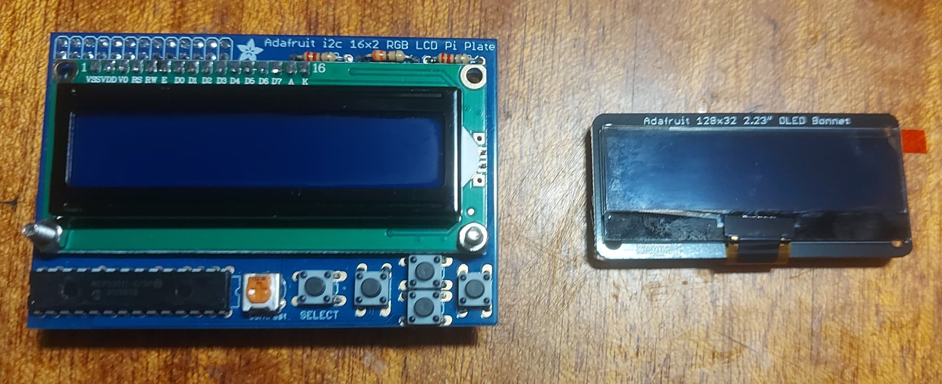
An Adafruit monochrome 16x2 display,
And!
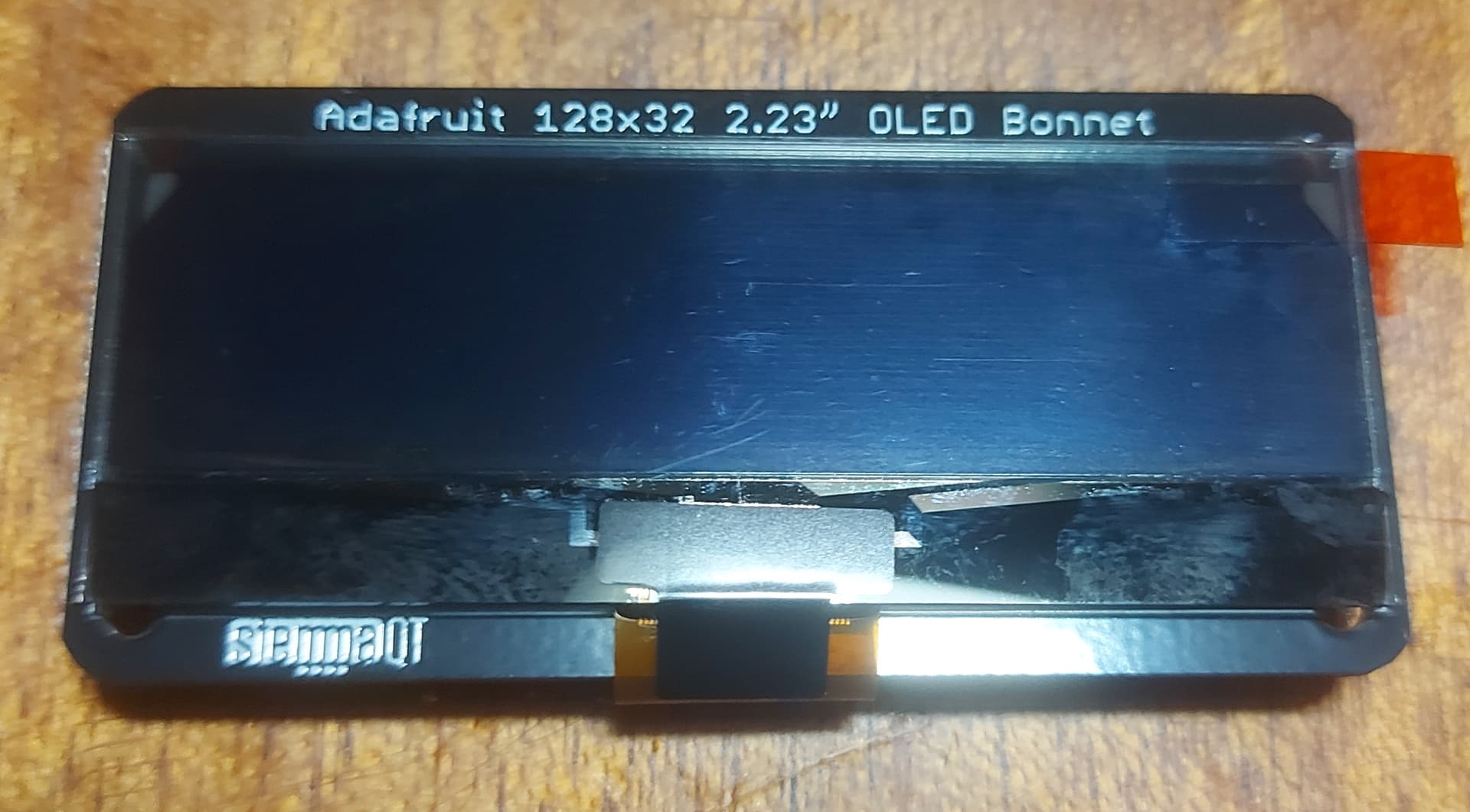
An Adafruit 128x32 OLED bonnet with
I don’t remember if the OLED is monochrome or RGB, but it’s interesting.
Here’s a picture giving a sense of scale to the Adafruit displays.
I’ve flashed three copies of GPG O/S, (one for each display), as I believe that downloading all the separate libraries and DTFs causes things to get “interesting” in strange ways.
This way I can test each one individually and determine which I prefer.
Is that a 40pin ribbon? Connectors on same side or opposite sides? I can never visualize pin 1 after routing cables.
p.s. Is that a 2m HT on the left? I’m surprised they let an American operate a radio…
DI invested in building a great API for both the gopigo and easygopigo package, but “forgot” to include acceleration management in the easygopigo API, by mounting the battery on the back. Dave has more central weight with increased moment by the added height, so even with the battery on the rear I cannot stop from max speed without a face plant.
The dual casters concept does not work for Dave in my home because the tile floors have “high center traps”
No.
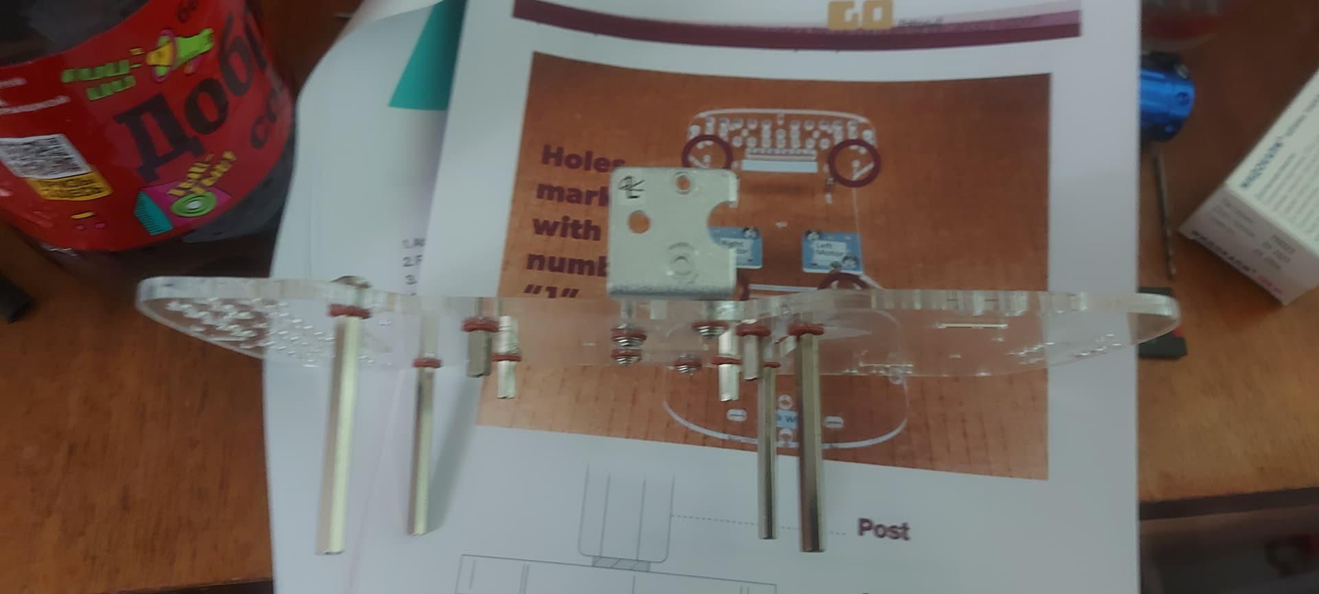
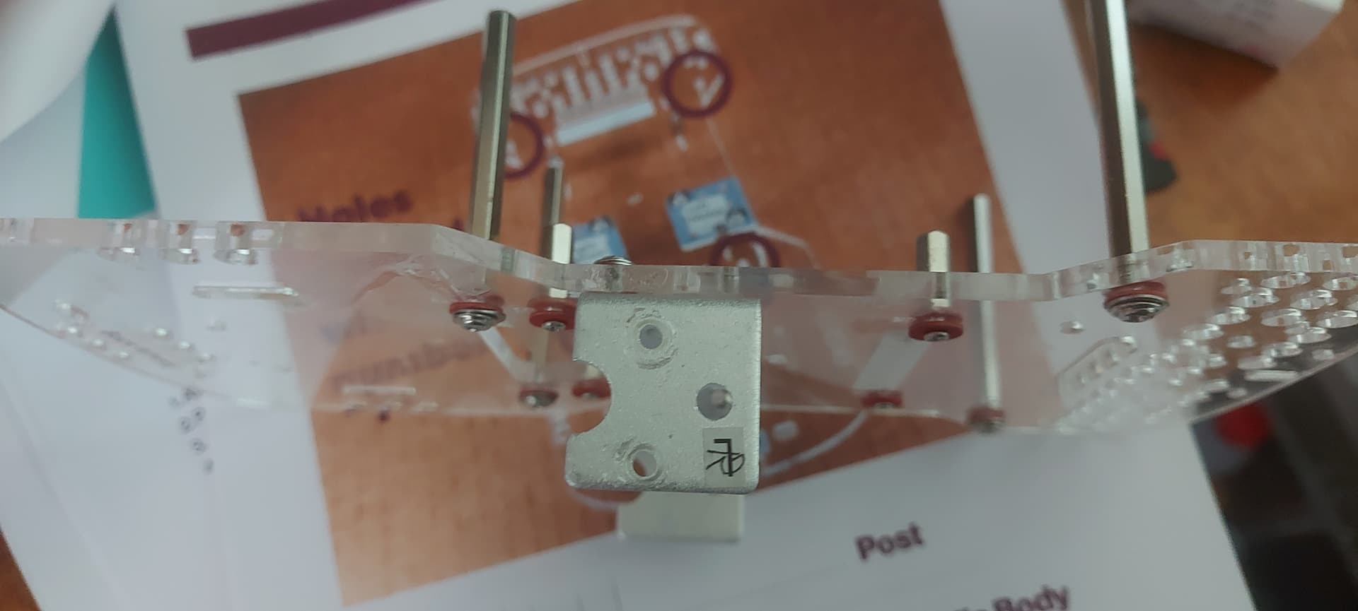
That is a “40 pin stacking header” as purchased from Adafruit. It has a 40 pin female connector with pins that are much longer than the normal connectors. It is either identical or extremely similar to the long headers used on the GoPiGo controller board allowing things to be stacked on top of it.
I bought some, and have a top plate with a cutout large enough for the 40 pin connector to pass through it. This way I can experiment with various add-on devices without having to keep removing and replacing the top cover each time.
Neither can I.
A set of 0.1 connector pins, (or breakout board’s male to male jumpers), and a DVM will show what is what.
I hate guessing and I hate letting out the “magic smoke” even more!
Great idea - way more convenient that way.
/K