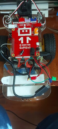
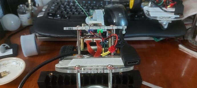
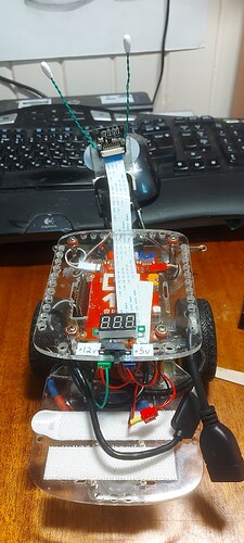
I have been adding things to my robots, many times by soldering to the necessary part of the circuit.
And then I need to change, modify, or repair something and I end up unsoldering everything - which stresses the PCB lands and causes problems.
Solution:
Add connectors.
Problem:
All the connectors look the same.
Solution:
Paint each connector a different color and the corresponding connector socket the same color.
Even if the connector isn’t used yet, it has a corresponding color that any mating connectors will use.
To prevent short circuits, any connectors that source a signal or are “hot” with a voltage are female. Any signal input or circuit that is using a voltage is a male socket. Male sockets are enclosed to prevent short circuits.
Red: +12 to the power boost to the Raspberry Pi.
Blue: +12 to the voltmeter.
Green: +5 and +12 to the voltmeter input switch.
Grey wire with on-line connector: Pi “running” signal to the power boost’s enable pin.
Green wire with in-line connector: +5 to the voltage input connector.
Every connection to any part of any board can be disconnected for rework or repair.


