I have connected a PPG sensor to the Raspberry Pi i^2c GPIO headers, I also have a GrovePi+ connected to the Raspi. The two devices are connected in parallel, i.e. the sensor is not connected on top of the GrovePi+. With this setup if i run i2cdetect -y 1 i get both addresses for the sensor 0x57 and the GrovePi 0x08 (i changed the address of the GrovePi because default 0x04 is now a reserved address on Bullseye 64-Bit OS so mine is now 0x08). Although the sensor is visible, when i try communicate over i2c i get an I/O error. This makes no sense, when the sensor is connected alone i am able to communicate. Is it possible there is a pull-up resistor in the GrovePi that causes this communication error but allows me to detect the sensor using i2cdetect?
@rorypmiley Suggest you check the schematic, and with a double~E conversant with Pi output current and impedance and the GrovePi+ I2C level shifter input load/impedance to see if tha Pi can support two I2C loads - it would appear from your test that it cannot, although I do remember someone posting success at stacking GrovePi boards, so perhaps you need to daisychain your sensor rather than treating the Pi as a hub.
I2C can work well for short bursts, and fail intermittently for longer or more complex interchanges. My robot experiences certain non-recoverable I2C failures with some sensors after working just fine for hours or days. It will always fail but when it will fail will be a mystery.
Hi Rory,
how is it connected? I’m not following.
Are you using the pins or the i2C grove connector?
@cleoqc I soldered wires coming from the SDA, SCl,GND and 3.3v headers from the Raspberry Pi.
@cyclicalobsessive I have looked at the schematic and I don’t believe the level shifter should be causing any problems, although i am not an electrical engineer and i haven’t had a module in electronics in 2 years, so my understanding could be primitive. I also saw the GrovePis stacked on top of each-other, although i don’t see how putting the sensor on top of the GrovePi would change anything as I was under the assumption that the headers on the GrovePi are continuous to the Raspberry Pi.
When digital circuits sort of work, it is often a matter of levels. Many circuits which are designed to work with either 3.3v logic or 5v logic input levels become brittle when the load on the 3.3v output driver increases. The output driver may not have enough oomph to get the pin to full voltage or may round the square rising edge making the channel less reliable.
I don’t know that this is your case; only putting a multi-channel oscilloscope (with high impedance probe) on the circuit will rule out over-loading an output.
It would be much better circuit design to move your sensor to one of the GrovePi+ level shifted I2C interface connectors so that the Raspberry Pi is only driving one input load (the high impedance GrovePi+ level shifter).
No, the RPI-SCL and RPI-SDA (from the GPIO connector)
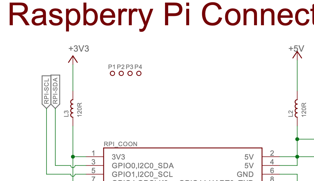
go through a high impedance level shifter
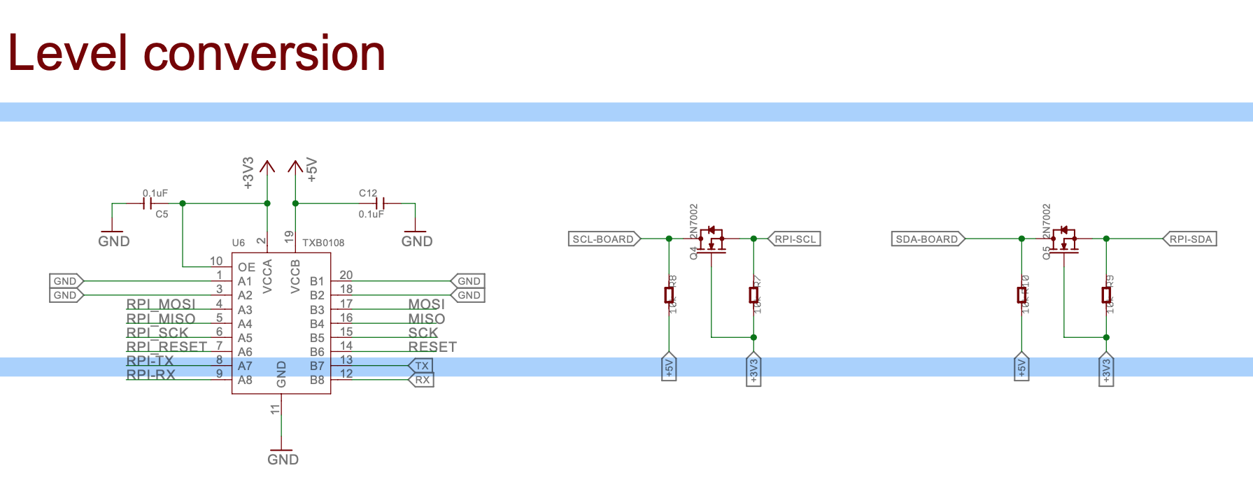
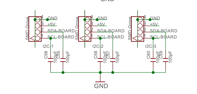
and then on to the Grove Pi+ I2C board connectors
BTW, while ModRobotics/DexterIndustries are no longer selling the GrovePi/GrovePi+, the circuit is a testament to the quality design of DexterIndustries that "KickStarter"ed the devices into existence.
Could you share the code that you’re using to communicate with the sensor?
@cleoqc
i2c = refdes117.REFDES117()
while True:
start = time()
red,ir = i2c.read_once()
##--------------------------------INSIDE THE REFDES lib------------------------------##
class REFDES117():
#Can find the address using bash command: “i2cdetect -a -y 1”
#default hard coded gpio pin 7, not requried unless bulk read
def init(self,address=0x57):
rev = GPIO.RPI_REVISION
if rev == 2 or rev == 3:
bus = smbus.SMBus(1)
else:
bus = smbus.SMBus(0)
self.bus = bus
self.address=address
    self.b02 = 0
    self.b02_bool = 0

    self.BPM = 0
    self.hr_bool = 0
    self.ibi = 0

    self.red_val = 0
    self.ir_val = 0
    self.signal = 0
    self.reset()

    sleep(1)  # wait 1 sec
    # read & clear interrupt register (read 1 byte)
    reg_data = self.bus.read_i2c_block_data(self.address, REG_INTR_STATUS_1, 1)
    print(f"[SETUP] reset complete with interrupt register0: {reg_data}")
    self.setup()

def reset(self):
    # Reset the device, this will clear all settings,
    # so after running this, run setup() again.
    self.bus.write_i2c_block_data(self.address, REG_MODE_CONFIG, [0x40])
def setup(self, led_mode=0x03):
    # This will setup the device with the values written in sample Arduino code.
    # INTR setting
    # 0xc0 : A_FULL_EN and PPG_RDY_EN = Interrupt will be triggered when
    # fifo almost full & new fifo data ready
    self.bus.write_i2c_block_data(self.address, REG_INTR_ENABLE_1, [0xc0])
    self.bus.write_i2c_block_data(self.address, REG_INTR_ENABLE_2, [0x00])

    # FIFO_WR_PTR[4:0]
    self.bus.write_i2c_block_data(self.address, REG_FIFO_WR_PTR, [0x00])
    # OVF_COUNTER[4:0]
    self.bus.write_i2c_block_data(self.address, REG_OVF_COUNTER, [0x00])
    # FIFO_RD_PTR[4:0]
    self.bus.write_i2c_block_data(self.address, REG_FIFO_RD_PTR, [0x00])

    # 0b 0100 1111
    # sample avg = 4, fifo rollover = false, fifo almost full = 17
    self.bus.write_i2c_block_data(self.address, REG_FIFO_CONFIG, [0x4f])

    # 0x02 for read-only, 0x03 for SpO2 mode, 0x07 multimode LED
    self.bus.write_i2c_block_data(self.address, REG_MODE_CONFIG, [led_mode])
    # 0b 0010 0111
    # SPO2_ADC range = 4096nA, SPO2 sample rate = 100Hz, LED pulse-width = 411uS
    self.bus.write_i2c_block_data(self.address, REG_SPO2_CONFIG, [0x27])

    # choose value for ~7mA for LED1
    self.bus.write_i2c_block_data(self.address, REG_LED1_PA, [0x24])
    # choose value for ~7mA for LED2
    self.bus.write_i2c_block_data(self.address, REG_LED2_PA, [0x24])
    # choose value fro ~25mA for Pilot LED
    self.bus.write_i2c_block_data(self.address, REG_PILOT_PA, [0x7f])

def read_once(self):
    # read 1 byte from registers (values are discarded)
    reg_INTR1 = self.bus.read_i2c_block_data(self.address, REG_INTR_STATUS_1, 1)
    reg_INTR2 = self.bus.read_i2c_block_data(self.address, REG_INTR_STATUS_2, 1)

    # read 6-byte data from the device
    d = self.bus.read_i2c_block_data(self.address, REG_FIFO_DATA, 6)

    # mask MSB [23:18]
    self.red_led = (d[0] << 16 | d[1] << 8 | d[2]) & 0x03FFFF
    self.ir_led = (d[3] << 16 | d[4] << 8 | d[5]) & 0x03FFFF
@cyclicalobsessive After toying around with an oscilloscope, the level shifter does not cause the kind of interference i am witnessing, also as my sensor is connected to the 3.3v side of the level shift it isn’t an issue with it operating at 5v.
I also connected my sensor to the 5V side of level shift and the interference persisted in the same manor.
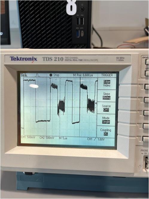
That looks absolutely nasty. @jimrh will need to help you but is away from his usual haunts at the moment. Watch this space for his electronics expertise on your problem.
If you can capture the signal at the RaspberryPi GPIO I2C data pin and clock pin for only the sensor, only the GrovePi+, and with both on the GPIO, you will probably be ready to work with him.
@cyclicalobsessive Yeah i investigated those at the time as well as watching the SCl pin from both the 5V and 3.3V side with just the grove connected and then just 3.3V with my sensor, all look perfect, interference only appears when both my refdes117 sensor is attached and the GrovePi+. Interestingly when I connected the Grove temperature sensor, no interference was present and i was able to see its i^2c address during i2cdetect. I can go back and capture them when I am back in the Lab. I don’t understand why this sensor and the GrovePi don’t play well considering the temp sensor seems to work correctly, leading me to believe it is not the fact i am on Bullseye 64-bit OS.
@cyclicalobsessive @cleoqc It appears i have found the problem. The GrovePi+ appears to use the Two-Wire Interface (TWI) and not i^2c to communicate. Although I am not certain, it could be causing this interference along the SDA and SCL wires when an i^2c sensor is connected. Although TWI and i^2c are very similar they are not the same. It is hard to find out that they use TWI considering all their main posts suggest it is an i^2c device. When looking at the seed studio post it hints at this when it mentions i^2c compatible however it uses TWI. I will have to investigate further this problem.
I agree.
Seeed studio’s circuits are often good, (±), but the support, (and as you have found), the documentation absolutely stink royally much of the time. They are also known to have compatibility issues, (as you have also found), because they often interpret specifications rather liberally, (being nice about it).
The oscilloscope display absolutely shows a collision between the two signals, as if the two wire interface device is not releasing the buss, (i.e. failing to tri-state properly).
Since I don’t know enough about the two-wire interface to have a competent opinion, I would suggest a web search to see what the actual behavior is supposed to be and if there is a way to make it work in a multi-device i2c environment. I would not be surprised if the actual two-wire interface reference design is supposed to tri-state the buss when not used, but I don’t know that and a more thorough study is recommended.
If the two-wire interface is not required to release the buss when inactive, then it absolutely cannot be used in a multi-slave device environment.
================================
P.S.
If you’re as OCD about well formatted posts as I am, this forum software allows the use of “&” HTML entity codes.
Viz.:
-
<sup> </sup> surround superscripts as in i<sup>2</sup>c = i2c
-
<sub> <sub> does the same thing, the other way as in H<sub>2</sub>O = H2O
-
creates a "non-breaking space that is not absorbed by the forum’s formatting. This lets you space paragraphs, or insert two spaces between a period, (.), and the beginning of the next sentence.
-
Other HTML entities work too. ° = °, µ = µ (as in µF), ± gives ±, and most other HTML character entity codes work. (Currency symbols, editor’s marks, other special symbols, en-dashes, em-dashes, etc.)
-
If you want to actually display the special entity codes as I have done here, preceed them with a backslash (\), to “escape” them as in \ (Here I had to escape both the backslash and the entity code giving me both
(\\)to display the backslash and\\\ to display the “non-breaking space” entity code. -
Individual back-ticks (`) can be placed both in front of, and behind, text that you want to be displayed literally, (an “inline” code-block").
-
In the same way you can use three back-ticks in a row, (```) before and after a multi-line code block to create a “paragraph” of unformatted text.
-
You can create quoted sections, (without taking your hands off the keyboard!), by typing in your own [quote] [/quote] blocks before and after the text you want to inset. I also use this for insetting a block of text as if it were within a text-box to improve readability sometimes.
Now that’s interesting… The GrovePi+ predates me and I do not have access to the design documents anymore, that means I can’t confirm your findings. However I have never heard of an I2C device that couldn’t be reached. This is quite puzzling indeed.
@cleoqc @jimrh Thank you very much for the support and the formatting info. I have decided to use a analog PPG and move on with my project as the deadline is coming soon. I wish I too had more time to investigate this issue. It is possible we will never know, but it might explain the list of i2c forum posts that don’t seem to have any meaningful answers.
Here is a relevant resource if anyone is interested, I didn’t read into it that much as i must move on but if anyone thinks they can hack it: https://ww1.microchip.com/downloads/en/DeviceDoc/90003181A.pdf
Here’s a gem from that document:
(This document makes it sound like TWI is a “customized” version of i2c that they can use to pick-and-choose what they want to support.)
I’d have to re-visit the schematics to see what, if any, pull-ups are used. However, it’s a known fact that the RPi doesn’t implement clock-stretching properly, as we’ve found with the Dexter IMU module.
There IS a “software i2c module” for the Pi, that bit-bangs the analog I/O pins - that implements clock-stretching properly - but I think it’s a Dexter kind-of-thing and you’d have to “curl” the Dexter libraries into your O/S to use it.
Because of this, (assuming the logic voltage levels are compatible), you may be able to use this module on an analog connector, (instead of the Grove), and implement the device that way.
@cyclicalobsessive is the current expert on i2c issues, and he can tell you all the “gotcha’s” - or you can search for i2c and read his excellent posts on this subject. Even if you decide to implement it a different way, the time spent reading his articles will amply repay you.
If, as the 'scope readings suggest, the TWI device isn’t releasing the buss properly, (or whatever), the device absolutely will fail to enumerate - possibly balling up the comm with other devices as well - causing the other i2c devices to either fail outright or do screwy things.
At least that’s my humble opinion.
Hmmm. . . .
I just had a thought. . .
Have you tried a different device? It’s not impossible that you got a defective one where one of the Tri-State MOSFET’s is leaky. I’ve seen that before.
yeah i tried another sensor and no difference
Maybe Adafruit and/or Sparkfun have something you can use as an isolation device, or even as the primary interface?
If that beastie doesn’t release the buss properly, you’re probably going to have to get some kind of isolation device, or something else that implements i2c correctly.
I don’t know of any kind of interface that tolerates a device that won’t release the buss.
Hi! I am new to the GrovePi+ HAT. Could you please tell me where I can find the schematics?
Ah, never mind, I found the schematic diagram: