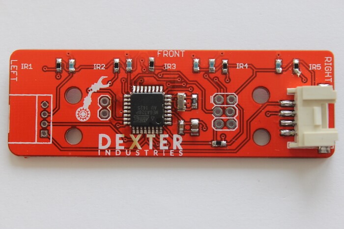
That photo is of an older version. The current one does not have a second header pinout.
There are two I2C ports on the GoPiGo3, but they share a single bus (Raspberry Pi hardware I2C bus). Additionally you can use each of the Analog Digital ports as another I2C bus, for a total of three buses. I2C on AD1 and AD2 is software controlled by the GoPiGo3, and it doesn’t suffer from the defect of the RPi HW I2C bus that prevents a lot of I2C devices from working (it’s a RPi HW bug related to clock stretching). The sensor drivers in DI_Sensors, including the dexter_i2c.py drivers, fully support the AD1 and AD2 I2C buses.
To use multiple devices on the I2C bus, you need to consider several things. At a protocol level, each device must have a unique I2C address. At the electrical level, the bus impedance must be within a usable range. Typically I2C is used for very short buses (often within the scope of a single PCB), with one set of pullup resistors. Adding additional devices to the bus will increase impedance (wire length adds capacitance, and each additional set of pullup resistors is added in parallel).
Depending on the devices, wire lengths, etc. it is possible to chain multiple devices on the I2C bus (easily two, but probably up to four or six). Some devices (including some of our newer I2C sensors) have traces on the PCB that can be cut to disable the I2C pullups, thus theoretically allowing more devices.
Almost all of our I2C devices have two grove ports to make it simple connect multiple sensors. Adding a second grove port to the line follower is something we intend to implement on a future version of the line follower.
The I2C connectors we use are called “Grove”. I think you can source them from Mouser, Seeed, Amazon, etc.
It is not possible to change the address of the line follower.
The distance sensor I2C address can be changed, but it’s through Software, and it’s not practical for most applications. Basically you would need to connect one sensor, change the address, connect the next sensor, change the address, and so on for each distance sensor you wanted to add. The I2C address is volatile though, so you would have to go through the process each time you powered up the sensors. On the back of the sensor PCB are some pads that an advanced user could solder extra wires to, and with some extra software, it could be possible to automatically set the addresses. Because of these complications, it’s much simpler to just use different I2C buses for each distance sensor (albeit with “only” three buses available).
The 2x3 pads on the line follower are for the ISP programmer to flash the firmware onto the microcontroller at the factory. The only two that would probably be useful to a HW hacker would be the 5v and Gnd connections (already available at the grove port).