The 3000mAh and the 6000mAh will both work. The 6000 one will last longer of course, but the 3000mAh is a better fit on the back of the GoPiGo.
Either one will resolve the issue of powering both the Pi and the LIDAR.
Btw, thanks go to @pitosalas for letting us know about this option.
I think that’s actually the same one that I linked to - it’s not apparent from the URL because both the 3Ah and the 6Ah batteries are on the same page. How did you get the bigger link? That’s certainly more helpful.
/K
There was a summary at the bottom of the page comparing all the different models, with a link that worked. Prior I kept trying to choose the 6000mAh version and copy the URL, but it kept giving me a link to the 3000 version - totally weird how javascript works I guess.
Word of advice: if you choose to go with this battery, do not trust the LEDs. They stay at 3 over 5 forever, and you have about 10min when it drops to 2 LEDs, and about a min, sometimes less when you hit one LED.
Very misleading.
But apart from that, great battery!
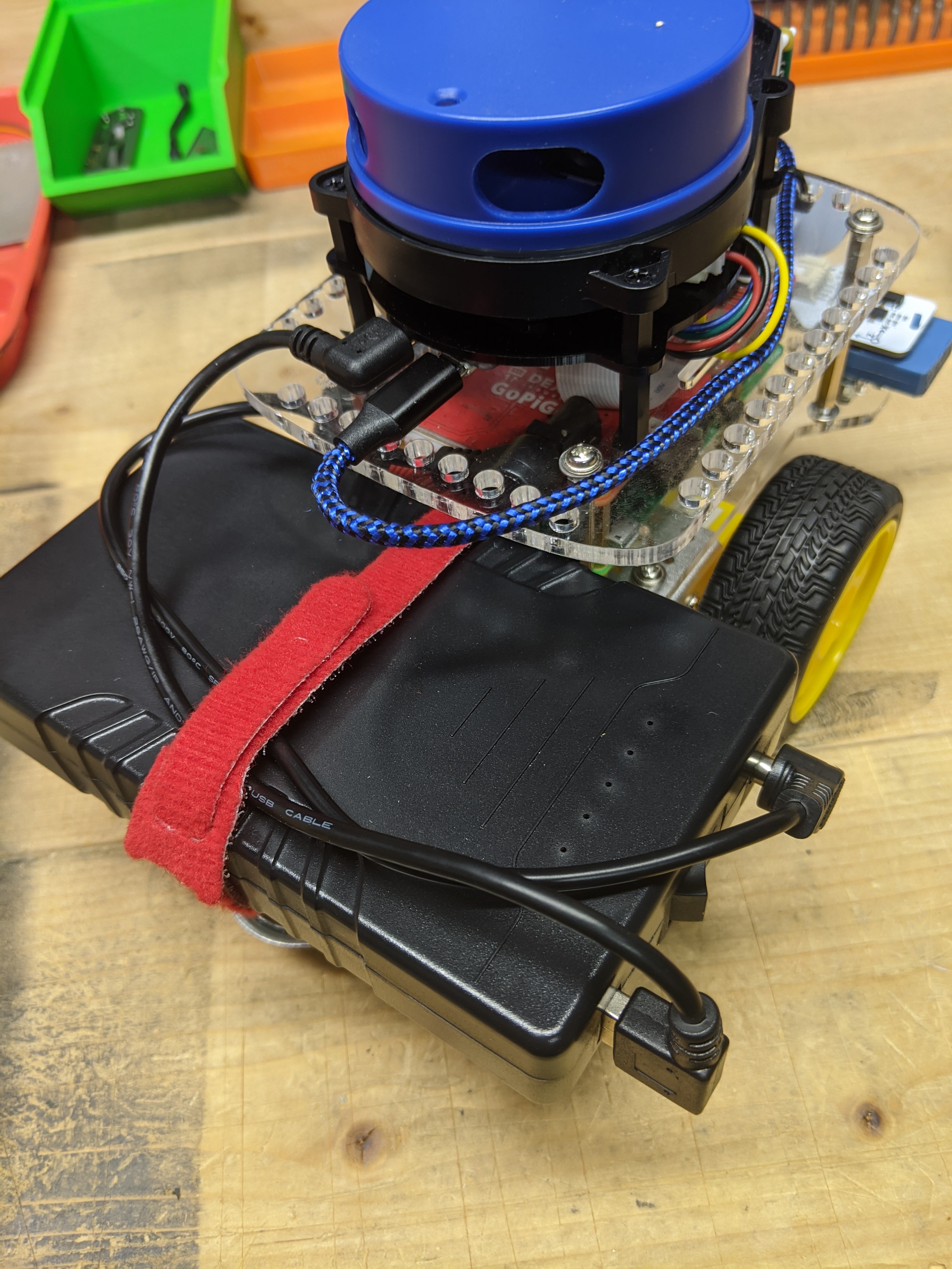
I couldn’t quite visualize it when I ordered the battery, so I’ve taken a picture of what it looks like on the robot. It stick’s out ~3/8" past the back deck. I got a couple of right-angle connectors to minimize how much was sticking out on the right side.
/K
@KeithW it will be interesting to know how ROS deals with turning uncertainty. I did a lot of turn accuracy and turn repeatability testing with batteries on the back deck and batteries closer to the virtual axle center, as well as max acceleration without lifting the castor or flat out tipping onto the nose.
(Also found the Pololu delrin ball castor to be greatly superior to the stock metal castor.)
Having the batteries just behind the virtual axle resulted in very good turn accuracy and repeatability (especially if all turns are made in the same clock direction). Placing the weight over the castor causes floor surface irregularities, such as floor board cracks or tile grout, to have a greater influence on turn accuracy and repeatability.
If ROS does some Kalman filtering with the encoders and IMU, perhaps it will not be as sensitive to battery placement.
Oh wow - hadn’t even thought of that. I’m just starting to look more into URDF modeling; no doubt this battery changes the inertia quite a bit. Don’t know how much that’s used in the real world (as opposed to just Gazebo).
I’ll have to look at the Pololu caster; thanks for the tip.
I’m in the process of building a small “arena” for my robot so that I have a more consistent environment for AMCL while I’m learning it. There’s enough furniture shift in my den, etc. that the mapping is a challenge. Of course the goal is to navigate freely. But for learning a confined, very fixed, space will be better (I think).
/K
It seems you got the 6000mAh battery? The 3000 one is smaller and fits just right (as in it doesn’t stick out). It’s also lighter than the original battery pack, iirc.
Did some testing of the battery. Initially I tried a program to do random wandering using just the front distance sensor, but the robot kept getting stuck with a side along a wall. Since I’m still learning navigation, I made it simpler and just went back and forth. I had written a monitoring package and included a program to create a node that writes the battery voltage to a log file every minute. Launch file ensured the lidar, camera, and distance sensor were running, even though I wasn’t using any of those sensor data. With that I got 4 hours of run time for the voltage to drop from 11.4V (which was a full charge) to 9.9V. But towards the end the robot was inconsistent - it backed up more than it went forward by just a small amount, so that it tended to drift backwards overall.
I had wanted to see if the battery would cut off by itself, but ended up stopping the robot before that happened since I really didn’t want to run the battery below 9.9V. Performance was pretty good for at least the first 3 hours, at which point it was down to about 10.2V. This is the 6000mAh. I’ve got the 3000mAh version on order - the bigger battery does seem to make the robot tail heavy.
I found it necessary to add a front-bumper to Charlie, connected to normally closed switches, to provide impact data that the distance sensor was unable to provide.
If necessary, you can program additional GPIO pins, beginning at pin 40, as auxiliary inputs for button sensors.
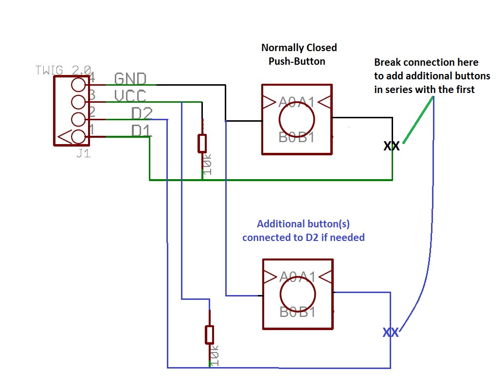
Here is a schematic for the normally-closed button arrangement I used for Charlie’s bumper:
Right now I am only using two buttons connected in series to D1, though an additional set of switches could be added to D2 if needed.
“TWIG” is a standard Grove connector.
VCC is connected to a source of +3v DC and ground is any convenient circuit ground.
Though shown connected via a Grove connector so that it can plug into the GoPiGo’s controller board, it can be wired to a female header and connected to any of the end GPIO pins you want.
I used normally closed switches connected in a pull-down configuration, (opening a switch causes D1 to rise to a logical “1”), because normally closed switches are more sensitive to impact than a normally open switch.
I can provide additional hardware help if you need it.
Good thought. I actually could have used the lidar to stay away from the walls, but I was being lazy and just wanted to do something quick and dirty. I have used button-based sensors in earlier robot projects - mostly using limit switches with an extension to increase the reach of the switch.
/K
Using both the LIDAR and impact bumpers is the way I’d go.
Though the LIDAR is good, it might not “see” everything, like a chair-leg for example. The bumper protects from “invisible” hazards.
Experiment:
Put a pole, (like a broom handle), of varying length vertically in various places within the maze and see if the robot can “see” it. Further experimentation will disclose the minimum height, and minimum diameter required for reliable detection from all points within the play area.
I was thinking pretty narrowly in the context of that particular set-up, but very fair points - LIDAR isn’t great for small/thin things, and won’t see anything above or below its plane of projection. Would be good to have some safety sensors that are more hard-wired to reality.
/K
You’ll see in the earlier pictures I had kludged together a mount for the distance sensor, but I wasn’t happy with it so I ordered this - looks tidier, and as I mentioned it’s easier to move temporarily.
/K