I bought the line follower device, the yellow and red LEDs are flashing when the GoPIGo is powered on.
I tried making a sample track with white A4 sheets and black tape. I try to run the sample python line_threshold_set.py file, but after pressing ENTER, it just returns blank and nothing else happens.
We need a little more information to find out what is not working for you. Can you try the following and post the results here:
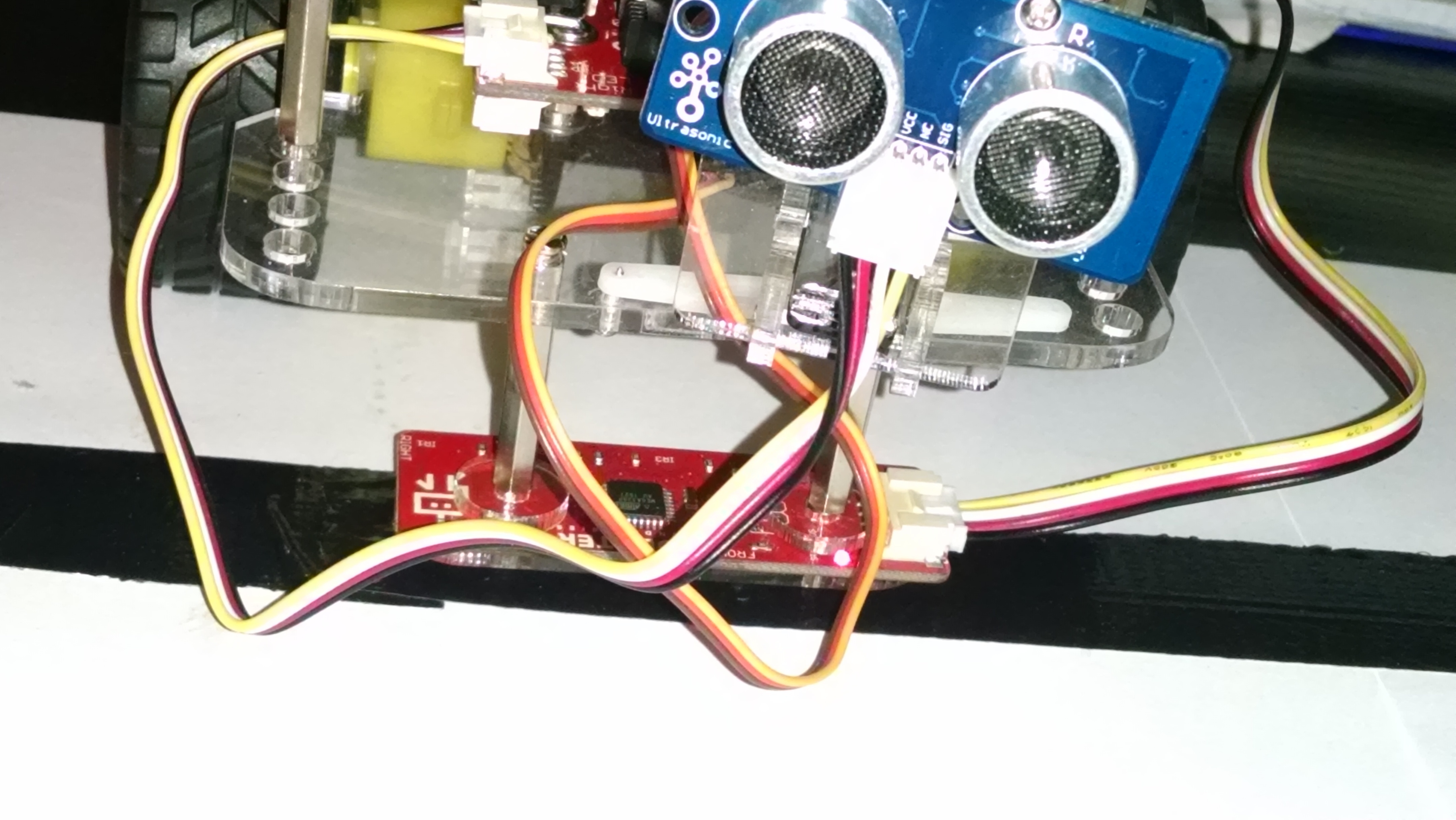
Send us a picture of your setup with the line sensor and GoPiGo . Make sure that the grove cable connects the line sensor and the GoPiGo I2C port properly and you can follow these instructions to assemble the line sensor on the GoPiGo.
Follow this guide to generate a test log and upload it on the forums.
Follow the steps given in this page and send us screenshots of the outputs that you get in each step.
I should be able to post up some images later tonight.
To answer a few questions;
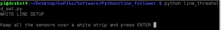
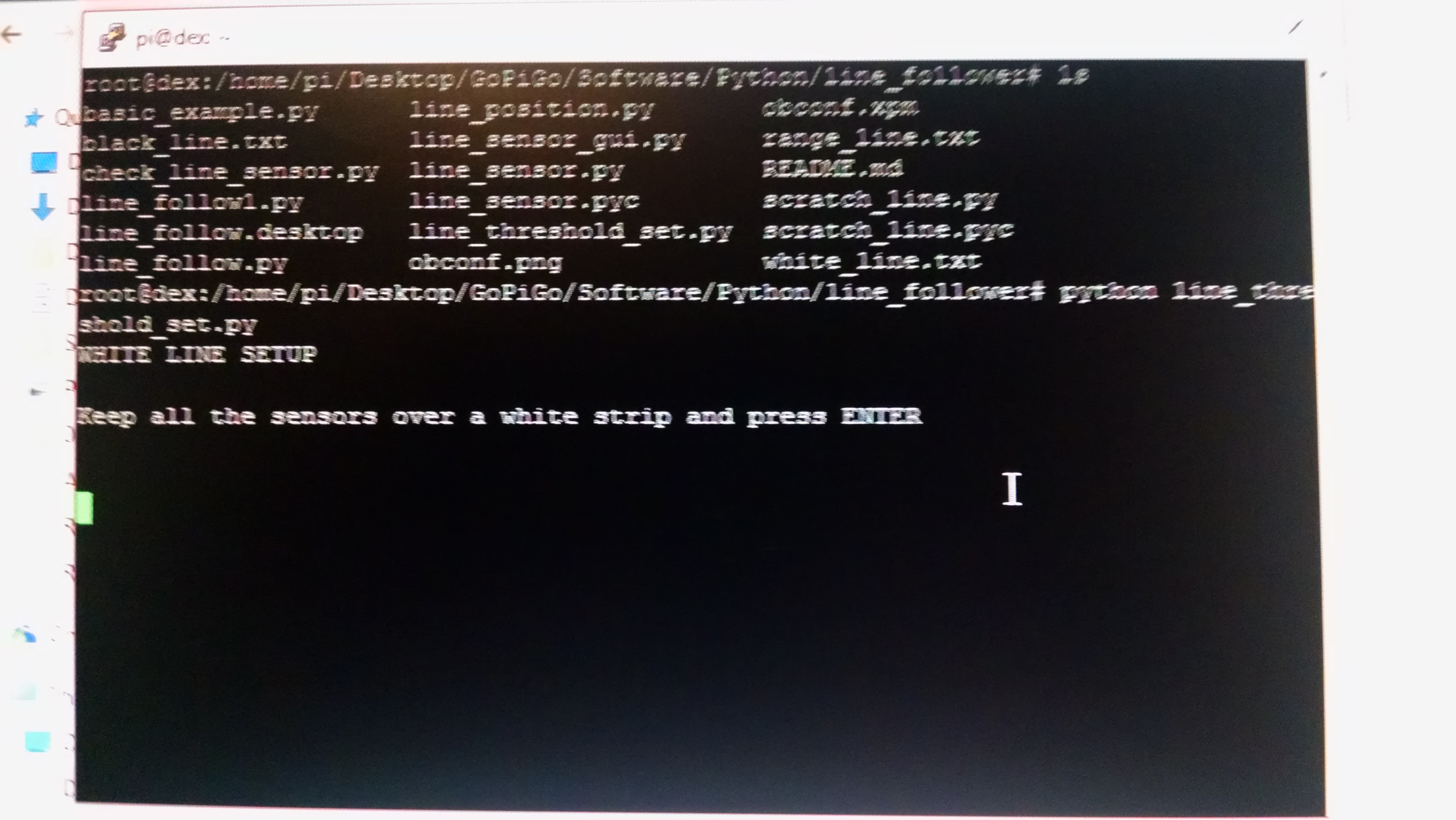
When I run “python line_threshold_set.py”
I do see "WHITE LINE SETUP
Keep all the sensors over a white strip and press ENTER"
After I press enter, it just returns blank information and no digits.
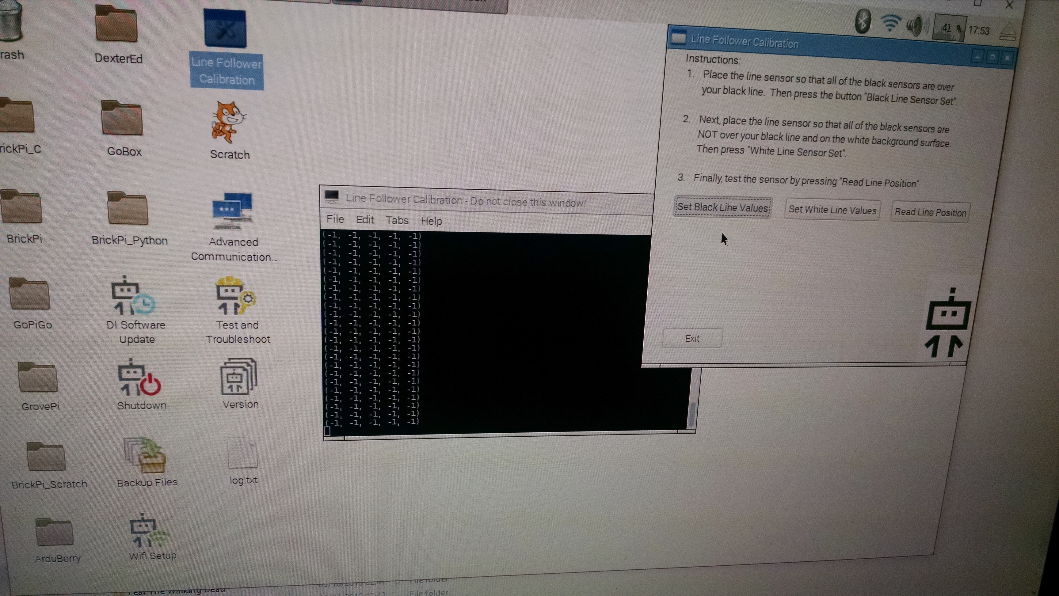
I have also tried the desktop “Line Follower Calibration”. When I go to run this and press either set black or white line, the application usually freezes and the black terminal screen returns
(-1,-1,-1,-1)
(-1,-1,-1,-1)
(-1,-1,-1,-1)
(-1,-1,-1,-1)
(-1,-1,-1,-1)
(-1,-1,-1,-1)
(-1,-1,-1,-1)
This is the same for either setting the black or white line values.
Thanks for sending the image. To make it even more clear, can you tell us if you have connected a 9V supply to GoPiGo while testing the line sensor. Can you also clarify if you have connected the line sensor to the I2C port of GoPiGo and send us a picture which clearly shows the connections between line sensor and the GoPiGo.
My apologies, I actually didn’t realise that there were another pair of ports directly underneath.
I have the line follower in IC2 port now. I can calibrate the black line when I place it over a black tag and pull the window blinds. The values are within 100 units of each other.
However, when i try to calibrate the white spaces, the values are completely off. Does a source of light in the room effect this?
@willphillips1984,
I’m glad you figured it out. The i2C port is kind of hidden all the way underneath. As for your question, you need a constant light source (or somewhat constant), and the same one for both parts of the calibration. You shouldn’t have to draw the window blinds to calibrate on the black line. Do make sure that the actual sensors are on the black line, the sensors are visible at the bottom of the line follower and they stand to the back. It’s quite easy to think you’re over the black line, but the sensors are too close to the white. It’s the sensors that should be smack in the middle of the black line when calibrating. I’ve made that mistake first. It’s also a good idea to calibrate each color (black and white) a couple of times. So press the calibration button a few times over black, then a few times over white. There’s no need to change the lighting situation at all.