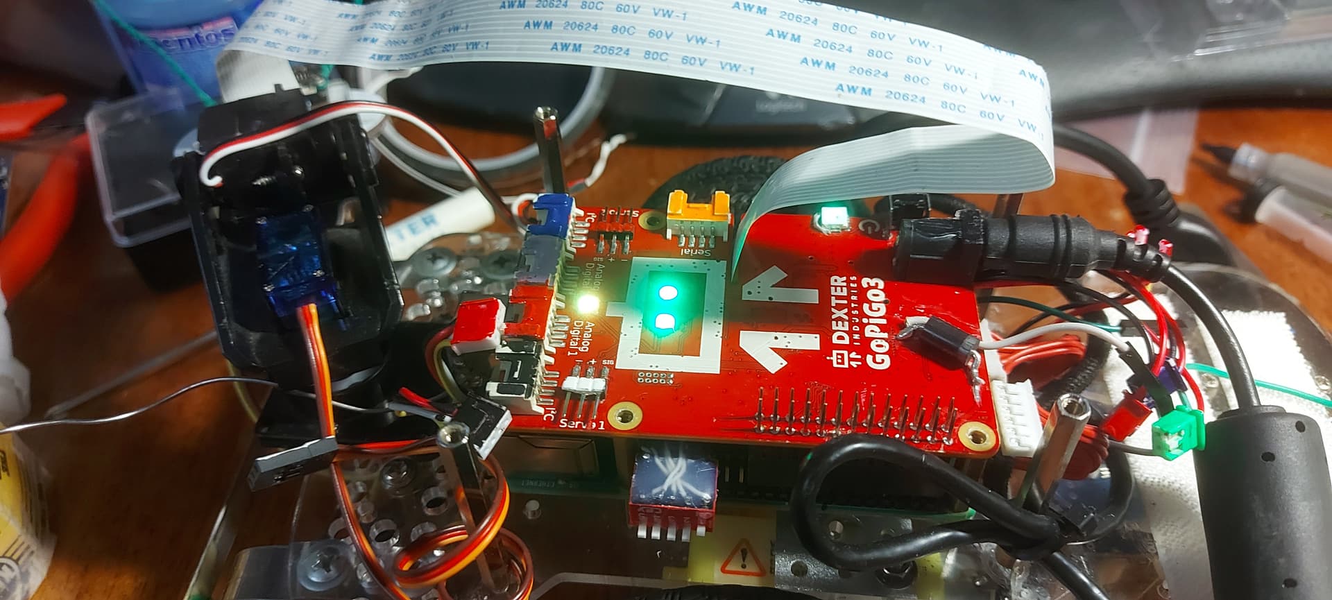
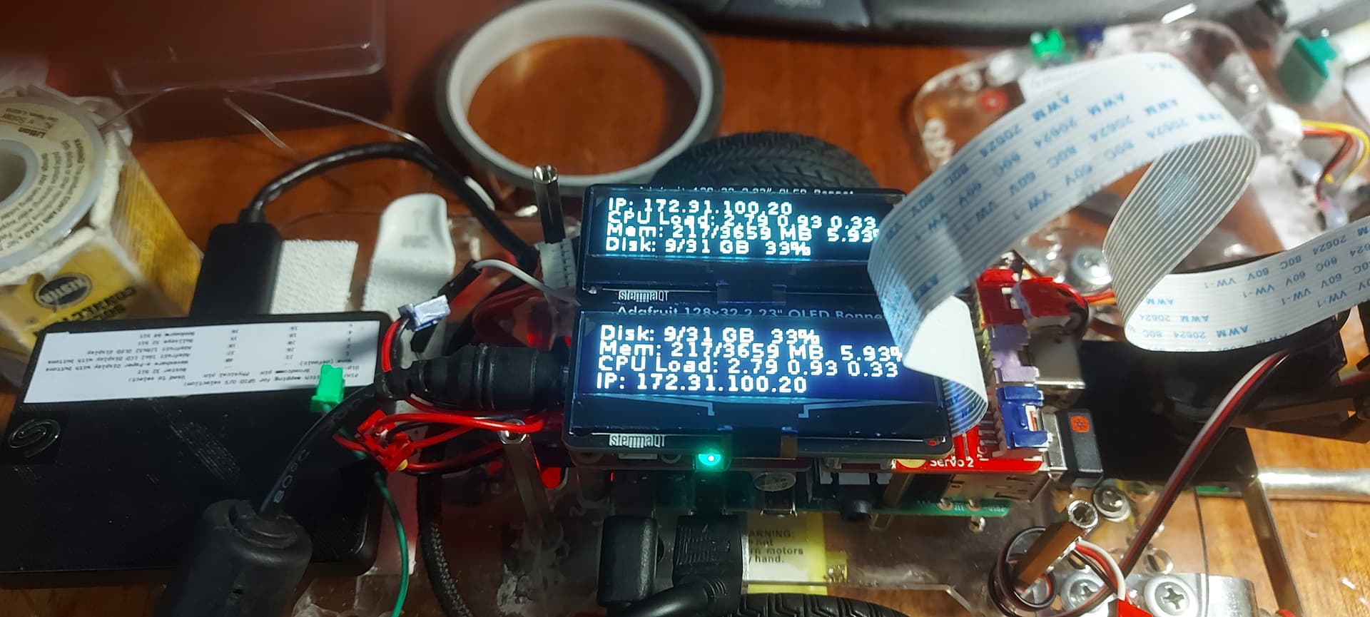
Loads on the GPIO (physical) pins 18 and/or 20 cause the robot to fail to start.
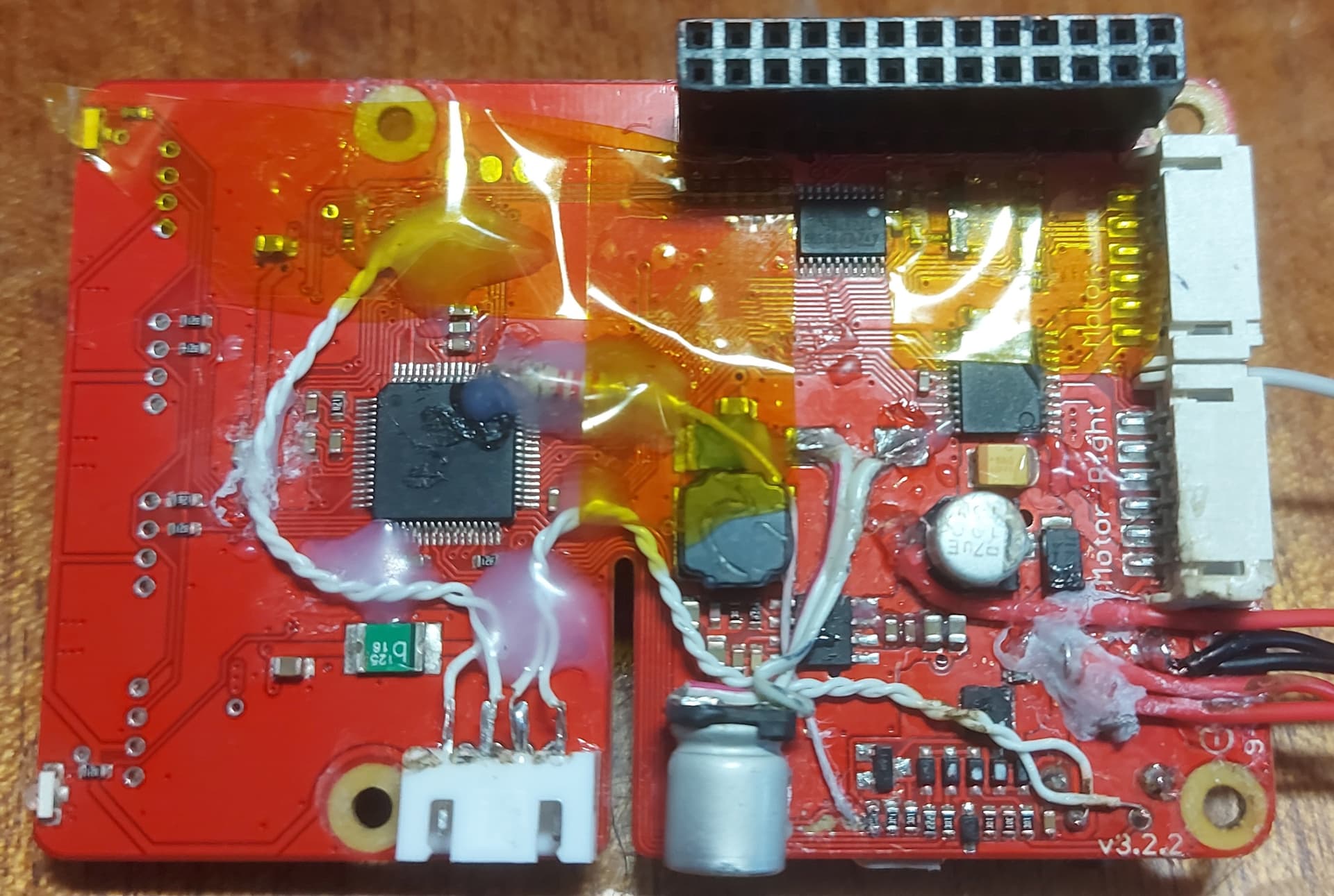
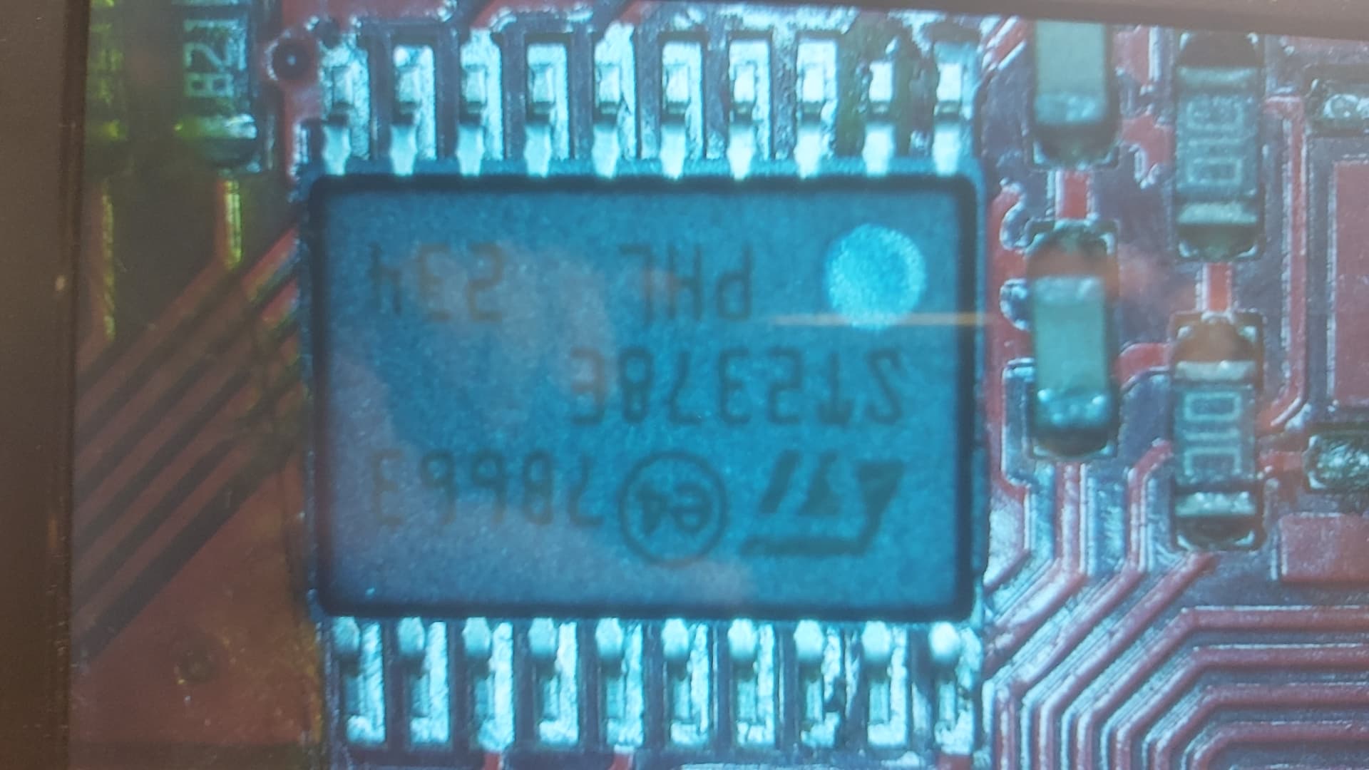
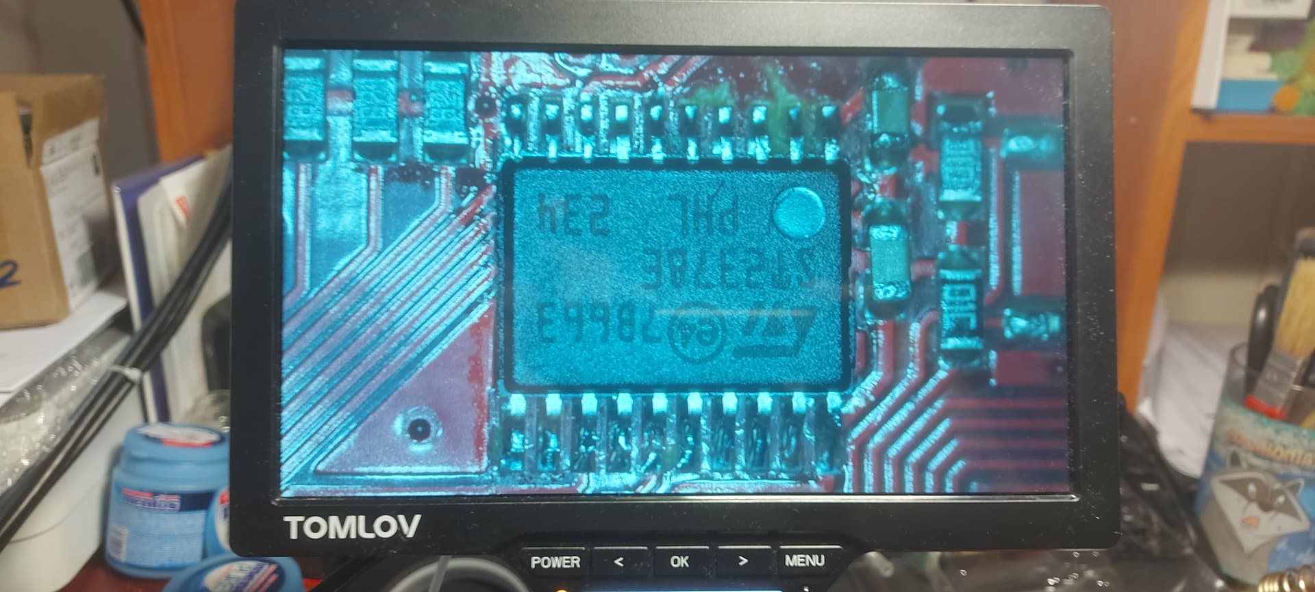
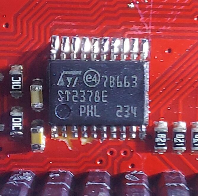
I suspect that the problem is with the st2378e level-shifter, (or the Atmel processor?), not being able to source the required current to multiple loads.
The GoPiGo controller will work by itself.
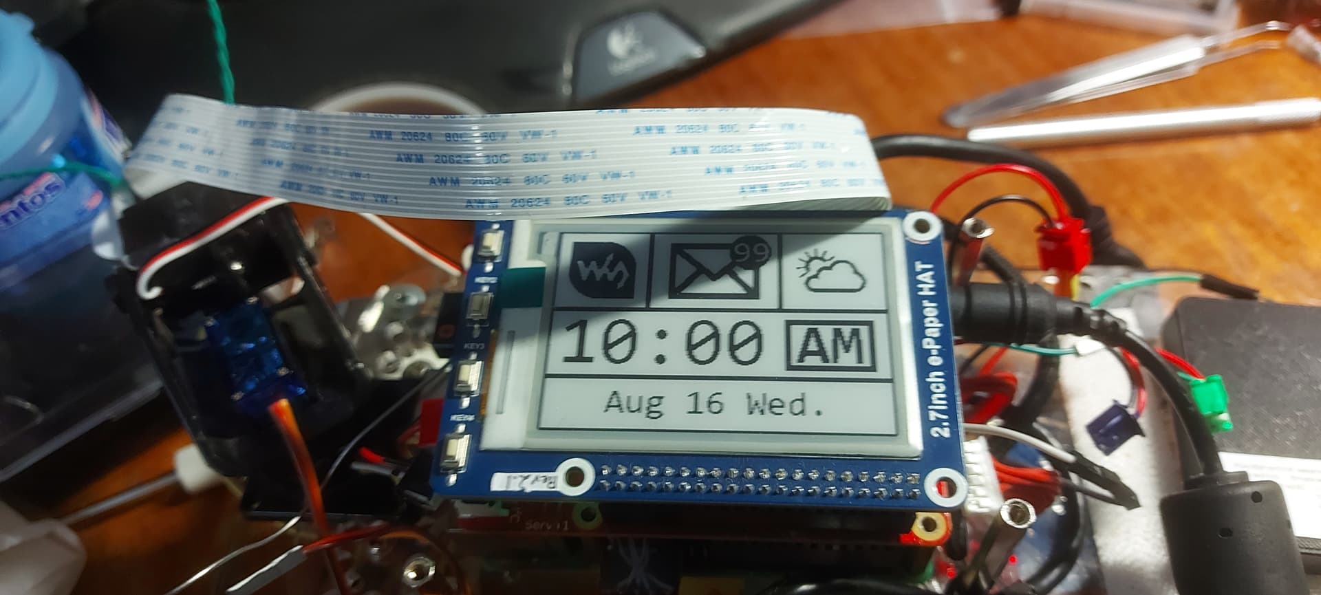
The Waveshare e-paper display will work by itself.
The combination of the two loads causes the robot to fail to start.
Ultimately I will probably need a new controller board for Charlie, but that’s not happening anytime soon.
Unfortunately these kind of piece parts are virtually unavailable here, and replacing them would be difficult to the extreme.
Good news: Things that don’t load those pins, (pure i2c), don’t affect Charlie’s operation.
More good news: Charlene doesn’t seem to have this problem.
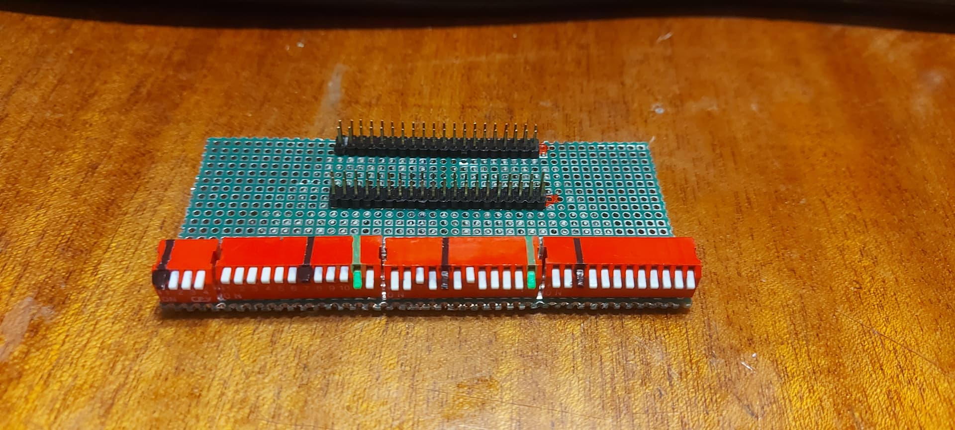
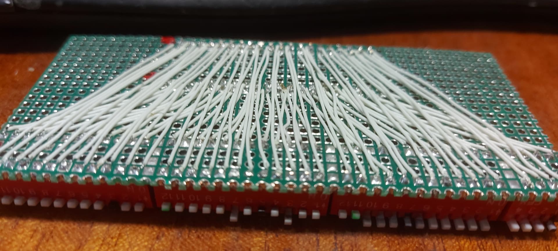
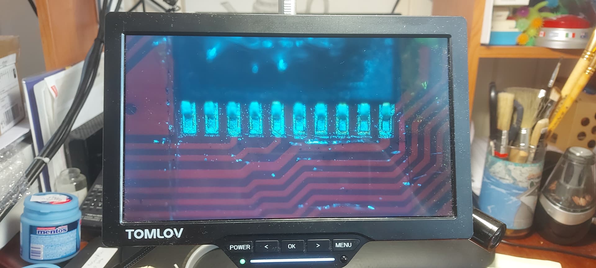
I did this in groups of 12 pins, (the dip-switches are grouped into twelve switches each except for the last one which is four switches), and checked each connection under my microscope after the end of 12 connections. Any questionable connection was measured with my meter.
There was a fair amount of rework where wires broke or connections didn’t work, but by grouping them into groups of 12 connections, it was easier to keep track of them.
I also did a rather quick-and-dirty continuity test from one header to the other after completion.
Ultimately Charlie’s functionality and mobility was reduced to virtually zero.
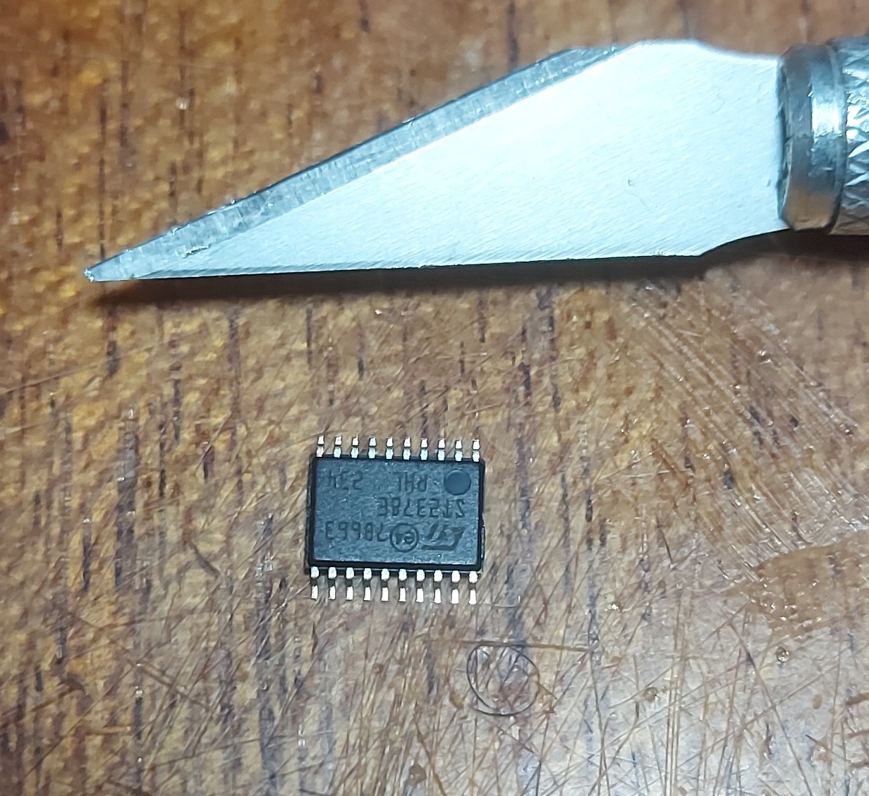
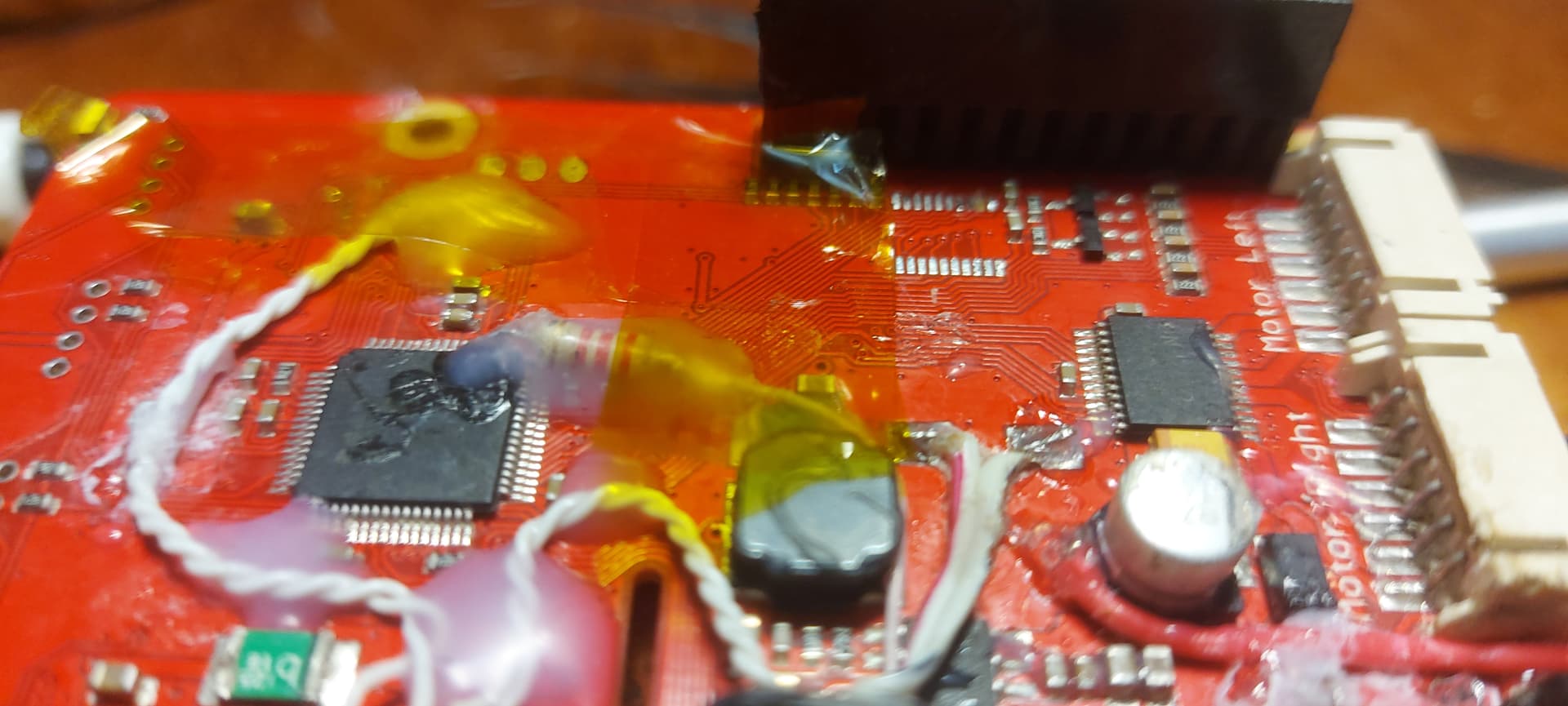
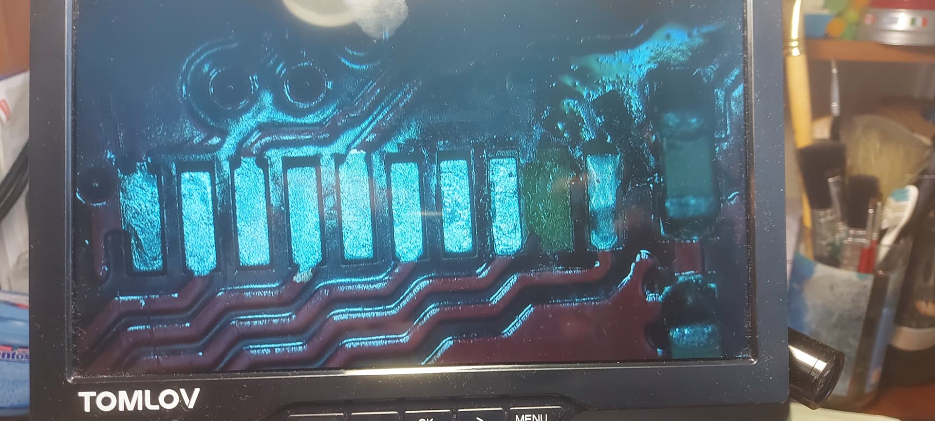
Extensive research lead me to believe that the ST2378E bi-directional level-shifter chip was well and truly toast. Which didn’t surprise me, what with everything I’ve done to Charlie all these years.
Though it was virtually impossible to guarantee that this was the problem, there was enough pointing toward that chip that I decided to replace it.
Ordered: Feb 4th.
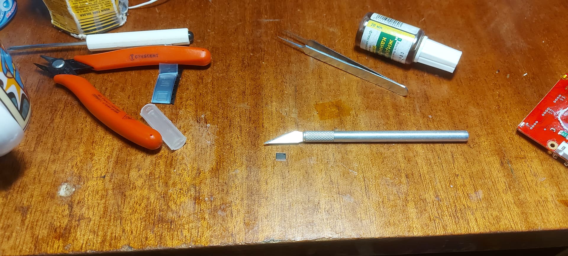
Received: Today.
Knowing how small they are, (and how much my hands shake), I bought three for something like $5 each.
The Waveshare 2.13" V2 and the 2.9" e-paper displays appear to work wonderfully.
However, the 2.13" V3 display doesn’t work on Charlie, but does work on Charlene.
Thought:
Maybe it’s because Charlene has a 40 pin interface and Charlie only has 26 pins?
Test:
Stack a 26 pin extension header on Charlene and test again. It works.
Translation:
There’s something different between the V2 and V3 displays. I’m going to look at the schematics and see what the difference is.
Note that signal pin pairs 2 and 4, (AFAIK being away from the schematics), used to carry the SPI data lines, but they were brought out to separate, discreet P/N channel component driver MOSFETs; presumably to increase the signal’s drive and stiffen up the rising and falling edges to make the signal’s cleaner.
As a result, these pins are now unused, so the one pad I lifted was a N/C pin and shouldn’t affect anything.