Greetings,
Recently, I attempted to build an Arduino based temperature probe using a DS18B20 thermal probe. The output is a multiplexed 74HC595 used to drive 4 seven segment displays.
The build works but, it is not able to read negative temps. In the code, I was able to move the decimal point over to read only tenths (000.0) instead of including hundredths (00.00) but I haven’t been able to successful remove the leading zeros. Attempts at using a mask bits have been unsuccessful. I have scoured Google for many moons trying to figure out how to correct this but examples don’t seem to work and I am getting lost in the programming and I’m left going in circles. Obviously, expert programmer I am not.  The DS18B20 has a range of -55°C to +125°C (-67°F to +257°F). Is there a sketch using seven segment displays like the schematic below that takes advantage of this wider range? I was using this as a starting point to build a deep freezer controller once I got past the negative temperatures and the leading zero issues but it’s a no go. There are plenty of kegerators out there but I don’t want to use an LCD. I chose to use seven segment displays in this configuration due to space constraints.
I built this using four separate displays instead of a single four digit because I don’t have one on hand but the wiring concept is essentially the same. The sketch I used that worked for me was from the following:
http://www.pial.net/arduino-controlling-a-4-digit-seven-segment-display/
Below is the sketch I used from this site along with changes I’ve made:
[code]#include <OneWire.h>
#include <DallasTemperature.h>
#define ONE_WIRE_BUS 2
OneWire oneWire(ONE_WIRE_BUS);
DallasTemperature sensors(&oneWire);
DeviceAddress insideThermometer;
const int ledPin = 13;// LED connected to digital pin 13
const int latchPin = 8;//Pin connected to ST_CP of 74HC595
const int clockPin = 9;//Pin connected to SH_CP of 74HC595
const int dataPin = 10;//Pin connected to DS of 74HC595
const int digitPins[4] = {
3,4,5,6}; //pins to control the 4 common anode pins of the display
const byte digit[10] = //seven segment digit bits
{
B00111111, //0
B00000110, //1
B01011011, //2
B01001111, //3
B01100110, //4
B01001111, //5
B01111101, //6
B00000111, //7
B01111111, //8
B01101111 //9
};
int digitBuffer[4] = {
0};
int digitScan = 0;
int soft_scaler = 0;
float tempC, tempF;
int tmp;
void setup() {
TCCR2A = 0;
TCCR2B = (1<<CS21);
TIMSK2 = (1<<TOIE2);
TCNT2 = 0;
pinMode(ledPin, OUTPUT);
for(int i=0;i<4;i++)
{
pinMode(digitPins,OUTPUT);
}
pinMode(latchPin, OUTPUT);
pinMode(clockPin, OUTPUT);
pinMode(dataPin, OUTPUT);
sensors.begin();
sensors.getAddress(insideThermometer, 0);
}
ISR(TIMER2_OVF_vect) {
soft_scaler++;
if(soft_scaler==15)
{
refreshDisplay();
soft_scaler = 0;
}
};
void refreshDisplay()
{
for(byte k=0;k<4;k++)
{
digitalWrite(digitPins[k], LOW);
}
digitalWrite(latchPin, LOW);
shiftOut(dataPin, clockPin, MSBFIRST, B11111111);
digitalWrite(latchPin, HIGH);
delayMicroseconds(400);
digitalWrite(digitPins[digitScan], HIGH);
digitalWrite(latchPin, LOW);
if(digitScan==1) //changed from if(digitScan==2)
{
shiftOut(dataPin, clockPin, MSBFIRST, ~(digit[digitBuffer[digitScan]] | B10000000)); //inserting the dot
}
else
{
shiftOut(dataPin, clockPin, MSBFIRST, ~digit[digitBuffer[digitScan]]);
}
digitalWrite(latchPin, HIGH);
digitScan++;
if(digitScan>3) digitScan=0;
}
void loop()
{
digitalWrite(ledPin, HIGH);
sensors.requestTemperatures();
tempC = sensors.getTempC(insideThermometer);
tempF = DallasTemperature::toFahrenheit(tempC);
tmp = int(tempF*100);
digitBuffer[2] = tmp/1000;
digitBuffer[1] = (tmp%1000)/100;
digitBuffer[0] = (tmp%100)/10;
//This is original code and was changed to the above to only show 1/10 decimal
//digitBuffer[3] = tmp/1000;
//digitBuffer[2] = (tmp%1000)/100;
//digitBuffer[1] = (tmp%100)/10;
//digitBuffer[0] = (tmp%100)%10;
digitalWrite(ledPin, LOW);
delay(500); //changed from delay(50)
[/code]
I ran into another blog that that appears to have successfully done what I am looking for but the build is over complicated. Some of the project appears to be inconsistent with it’s code and I find the code difficult to dissect to rewrite for a single sensor and single display. It can be found at:
http://mskvorc.com/blog/2012/05/arduino-temperature-sensor-box/
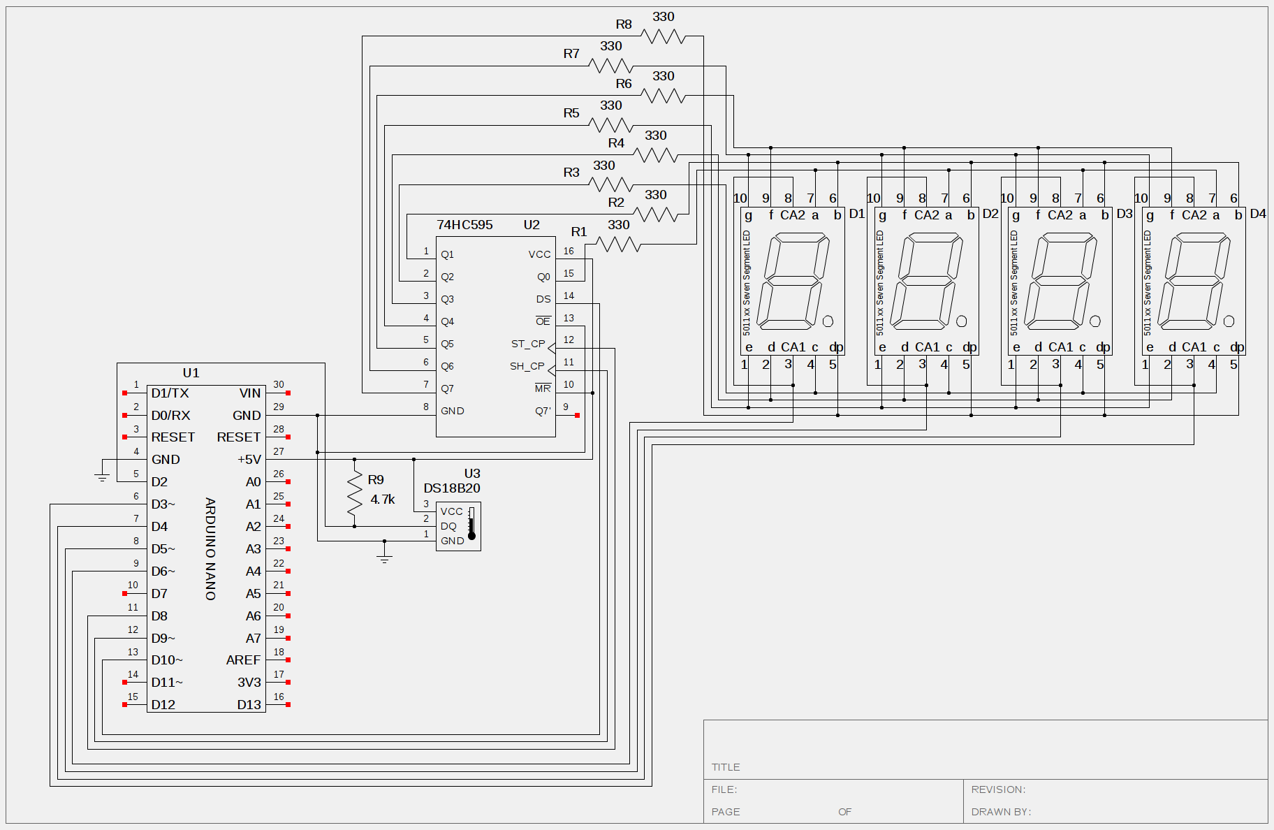
I have included the schematic of my build below. Any help would be most greatly appreciated. Many thanks in advance.