My Visions for Vision Just Went Dark

I saw a neat video of a robot finding and lining up with its dock using three large circles and OpenCV

So I thought I’d try that with Carl. Now Carl can already line up +/- 2 inches of the docking centerline, but that kind of precision does not make for reliable docking. Carl needs +/- 0.5 inch alignment to the docking centerline, I think.

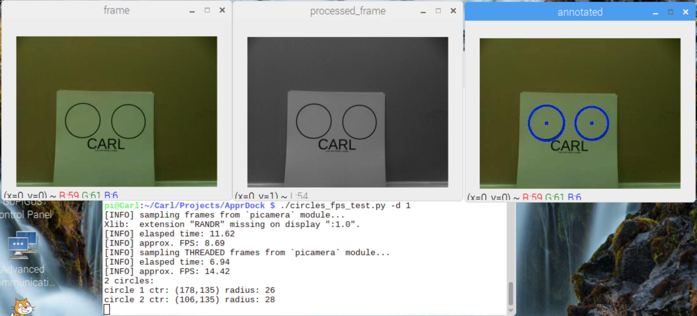
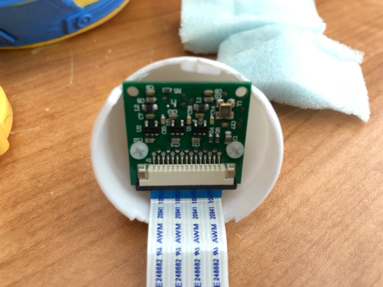
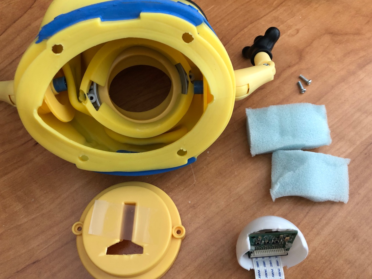
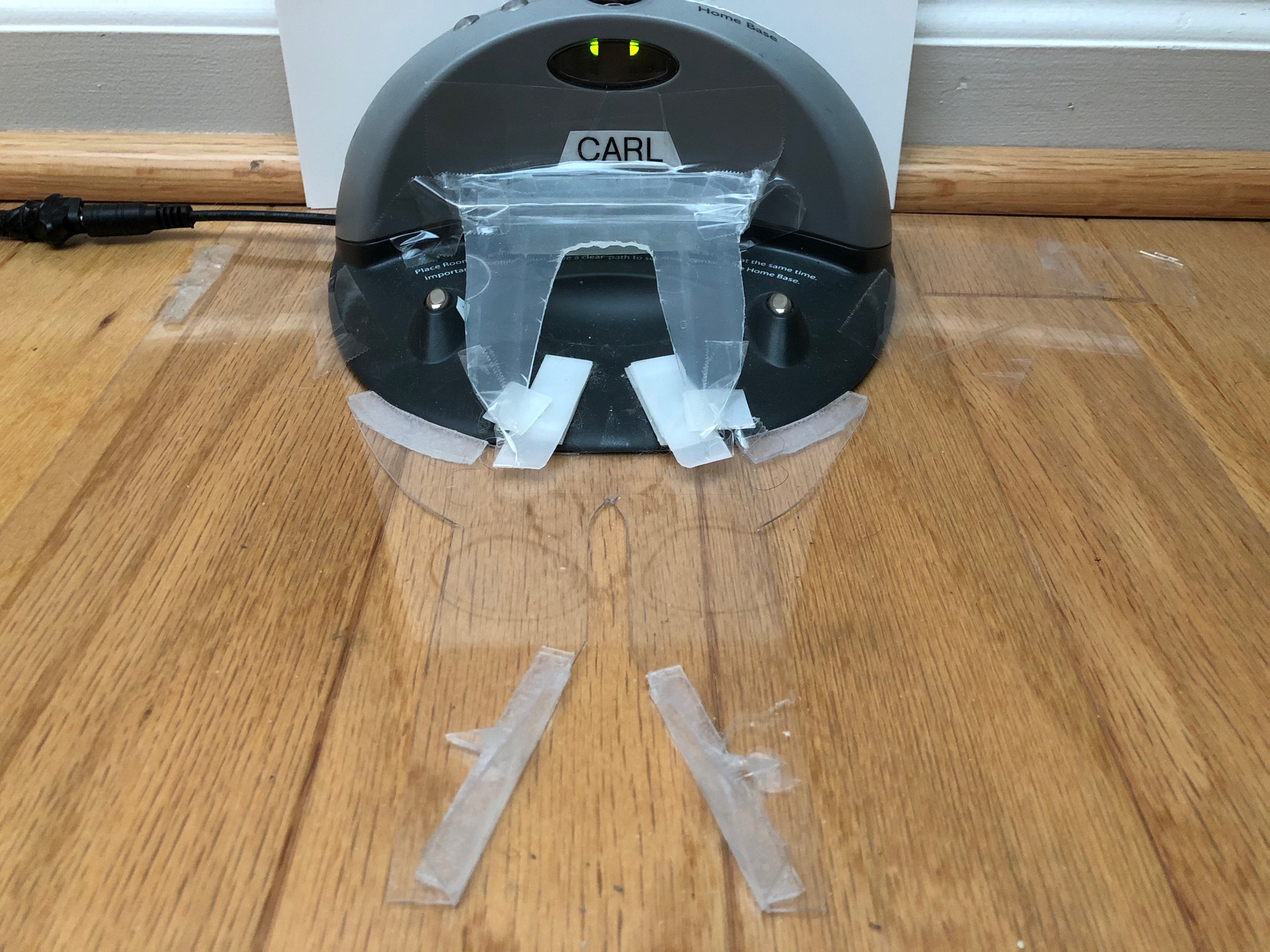
I created the appropriate sign for Carl to use, with two 3" circles on 4" centers, and proceeded to investigate what Carl “sees” when he is lined up and when he is 4" off center.

Here is what he sees when 16" from the dock:

And here is what he sees when 40" from the dock:

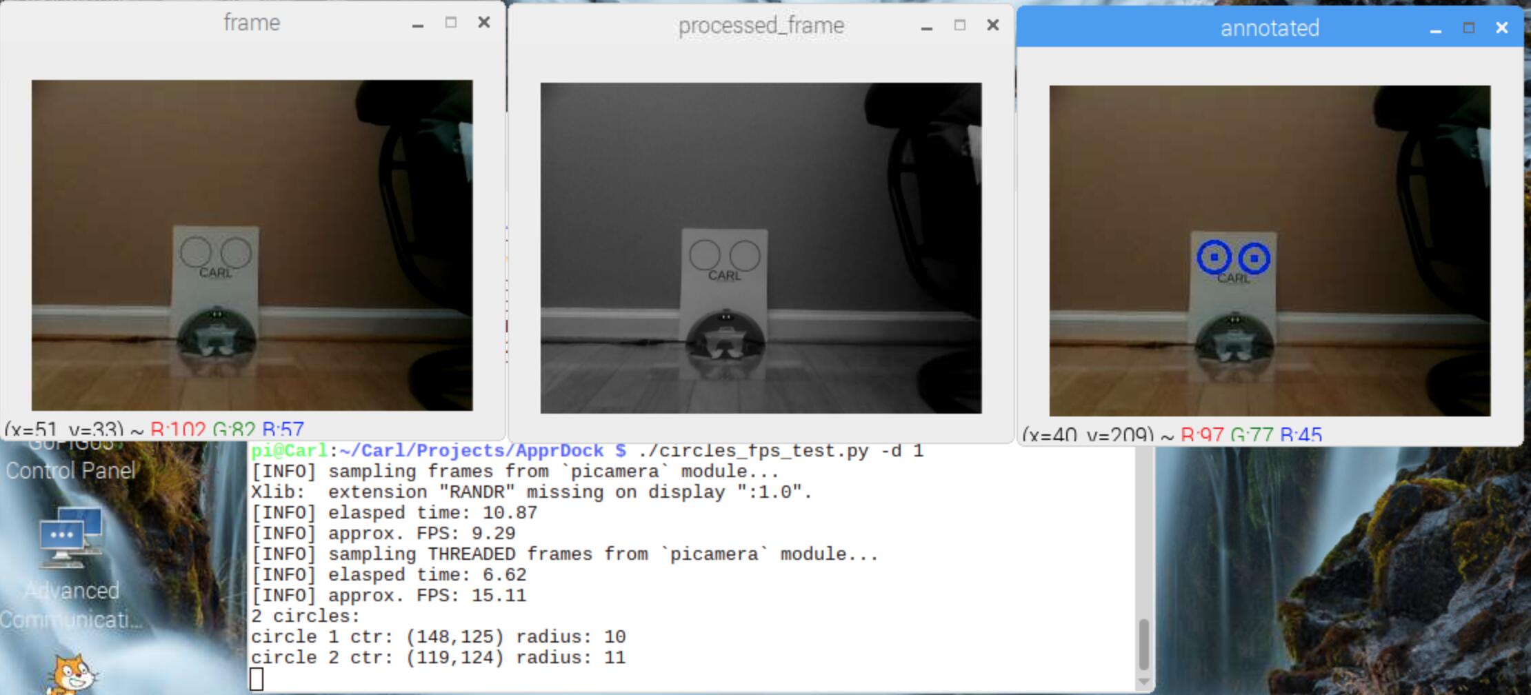
The circles radius changes by about 17 pixels in 24 inches or 0.71 px/inch when using 320x240 resolution video from the picamera.

Here is the “experimental result” from 4" to the right of center at 40 inches:

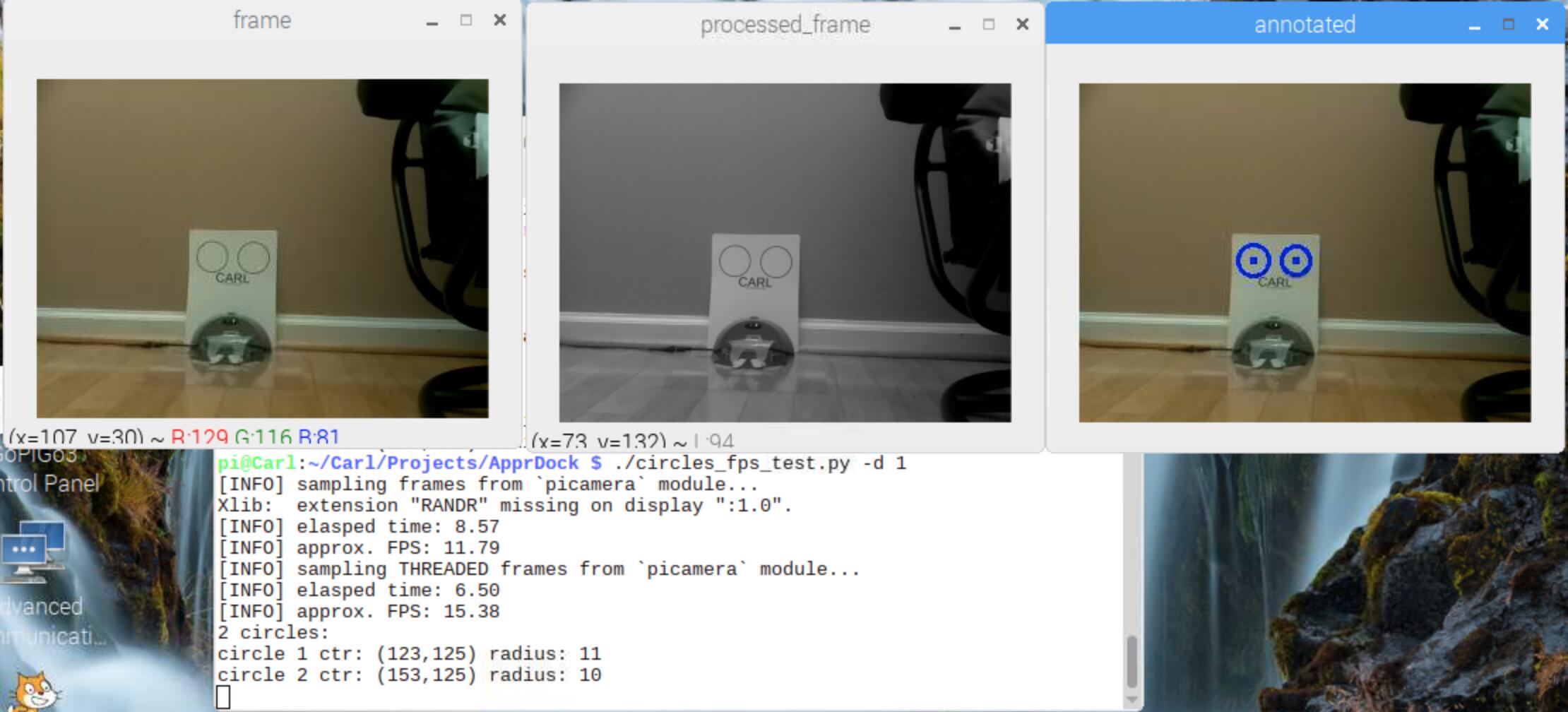
Circles lined up are left: 11 right: 10 pixels radius,
and circles when 4" to the right of lined up are left: 11 right: 10 pixels radius.
How come the same?

Now I need to determine what is the difference in distance to the right circle versus to the left circle when Carl is not on the centerline. If Carl is only 2" off center when 16 inches from the dock, the difference in distance to the right versus to the left circle is 0.37 inches.

Uh oh, I’m starting to see the problem here. Difference 0.37 inches * 0.71 pixels per inch = 0.26 pixels. Even if I bump up the resolution to 640x480, I get only one half pixel. This is for 2 inches off center and up close.

The difference in hypotenuse distance when 2 inches off center at 40 inches away is only 0.15 inches which is 0.1 px at 320x240 or 0.2 px at 640x480.

No way I’m going to be able to navigate to +/- 0.5 inches of the centerline using the circles.

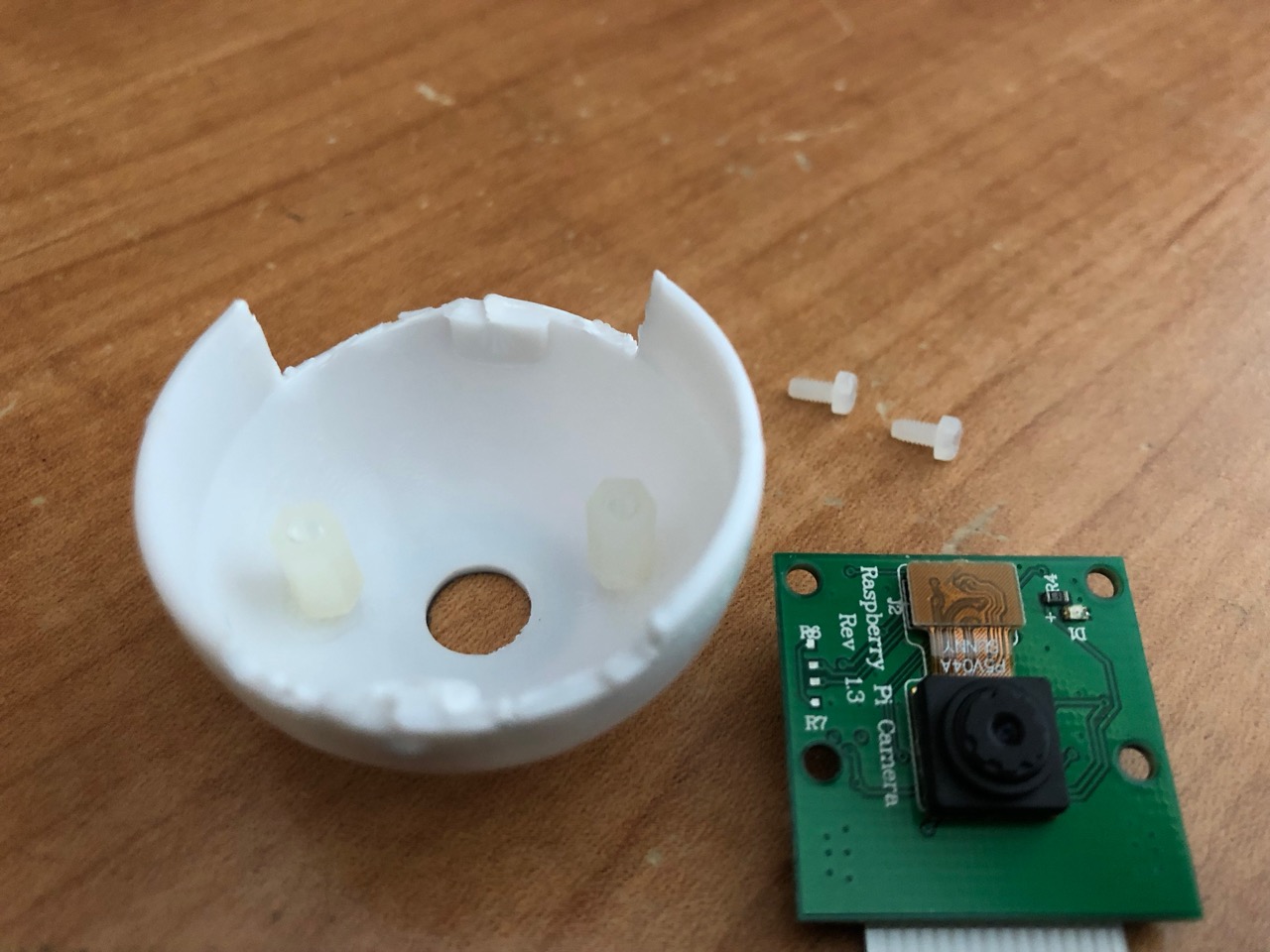
Looks like Carl’s one eye is just not as good as I was hoping for.

p.s. The bot in the video has extensive physical tolerance for the final docking, as well as a middle-forward-extended-circle, and a floor crack in the center that might have been better than the circles.

1 Like

I would expect the accuracy from a distance to [vacuum severely], but wouldn’t that improve as he gets closer?

Then again, if you need point accuracy to some negative exponent, is Carl’s eye exactly  set absolutely square, plumb and with no rotational offset in any of the three axes?  If you need that kind of accuracy, even a teeny-tiny aiming error of the eye will cause HUGE variation.

Just had a thought:
Can you place Carl some reasonable distance from his markers, set him 90, 90, 90 to his dock and center-line, and then adjust the camera for equal circles?  I’ll make a Big Pinky Bet with you that the angular difference is about 2/3 of a smidge. (± a hair or two.)

Nope, but I got that covered. Just wasn’t using it for the testing.

CAM_TILT = 2.0  # 1.53
DEFAULT_H_FOV = 55.5

# fixTiltOCV(image)
#             retuns an OpenCV image array rotated to correct camera mount error from horizontal

def fixTiltOCV(image):
    # Note: extra pixels will be black
    (h,w) = image.shape[:2]
    center = (w // 2, h // 2)
    M = cv2.getRotationMatrix2D(center, CAM_TILT, 1.0)
    rotated = cv2.warpAffine(image, M, (w, h))
    return rotated
1 Like

Cool!

But how does all that code know when he’s 0, 0, 0 to the center line?  Have you considered a couple of fine-pitched machine screws on the horizontal and vertical axes?

If I were messing with something like that - I’d put some mechanical “trim” on the eye’s horizontal and vertical axes, (like headlamp adjusters), then include the software, (or maybe skip the software altogether), trim for equal circles with the software off, and then turn it on.

All hope is not lost. I’m going to investigate using the directional green LEDs on the dock from far away and see if driving with those might get me on center.

And if that doesn’t work, I’m gonna lay down a centerline and just line follow it home.

1 Like

Just make sure the center-line is golden colored and has small black pattern lines in it periodically.  When Carl’s lined up and seeking, he can sing “We’re off to see the wizard. . .!”

1 Like

Man, I was just happy with gluing some standoffs. I may have earned a Mech. Engr degree, but it doesn’t mean I can actually build squat! Put a screwdriver in a software guy’s (the real me) hand and he’s more likely to hurt himself than fix anything.

That scotch tape and two foam pieces are the “mechanical trim”:

Truer words were never spoken and my wife goes running for the bandages when I pick up a sharp tool.  That doesn’t keep me from trying and my hands look worse than an auto-mechanic’s hands!

As for “the real me”, I’m first and foremost a hardware guy.  I’ve been taking things apart and (trying to) put them back together again since before I knew which end of the soldering iron got hot.  My first major project, (when I was still a kid), was scrounging parts out of the neighbor’s trash cans on trash-day and building myself a go-kart engine.  My dad confiscated it when he accidentally pranged the lawnmower’s engine on a half-buried iron-pipe hidden in the grass.  I was tickled pink when it started right up first time, but I was disappointed as hell because there went my go-kart!

If you really want to try mechanical adjusters, I can’t do the entire design for you, but a couple of 2mm or so fine thread machine screws and nuts, a few needles and a handful of plastic flossers work wonders for making pivoting screw-mounts.

Drill a 1mm hole in the center of the opposite sides of a few nuts, stick needles in them with epoxy or crazy-glue, (needles are stiffer and stronger than pins), and use the needles to poke holes into a couple of the plastic stems, and use the stems as bearings for the nuts to swivel on.  Take the springs out of a couple of dead “click-type” retractable ball point pens to use as tensioners on the screws, and you’re well on your way.

Have you thought of a couple of guides extending out from the dock itself?  Put little plastic hands on the ends and you have a dock that welcome’s Carl (ahem!) “with open arms”!. :scream:

Sort of, but they are not as effective as I hoped:

My total lack of building skills really hold Carl back.

1 Like

. . . .and my total lack of programming skills holds Charlie back too.  Hey!  If you don’t mind working with a certifiable Nut Case, we’d make a great team!  (Then again, I hear that long-distance relationships never end well. . . .  :laughing:)

1 Like

I was thinking of bent clothes-hanger wire extended out from the sides of the dock, then make something shorter than your guides to “tuck him in”.  You need thicker plastic.  Maybe some 1/8th or 1/16th foam-core board from Staples?  A scale and compass from your old college drafting set would help with lines and curves.  A stiff box cutter will make accurate cuts.

You may also need to guide the rolling wheels as well as his rear caster.

1 Like

The fact that neither of us has mounted the 3D printer challenge says we’re both “ol’ timers.”

They have laser cutters and 3D printers in every school now and the kids really build stuff.

To that point - I was looking at HuskyLens today. $45 and 230mA gets you line following, trainable face and object recognition, color tracking. And I’m still trying to learn how to do these things one line at a time, refusing to add to Carl until he knows how to use what he has already.

1 Like

Cool beanies!  If I had the programming skills, I’d get one.

And for $230 (CN), you get a butt-ugly 'bot with a piss-ant Arduino board. . . .

I don’t think Dexter has any sample code for it yet, though.

1 Like

This all gets back to where I started. Every car around the world has a standardized refueling eco system. Robots Unite! Demand a standardized juicing system, or you’ll never gain your freedom.

1 Like

Preach it brother!  Preach it!

I wouldn’t hold my breath though - it was only after the FTC threatened anti-trust action against the mobile phone makers that they got their charging port act together.

However, your main problem isn’t the “juicing” part, it’s the positioning accuracy part too.  If all you cared about was getting Carl charged, you could change the width and shape of the charging pads to accommodate several degrees of drift.

Then again, knowing how well you pull code out of thin air, you could probably use a pair of tight-beam IR LED’s spaced a few inches apart and another Line Follower board, facing forward, to “zero in” on the beacons.  Put a half-dozen IR sensors on each side, write “a few simple lines of code” to simulate a phased-array radar receiver, and you’ve got it knocked! (laughing!)

That depends on if you are right-handed or left-handed, have a pull-tab in the car under the seat, or behind the dash, or under the steering wheel, or even in the passenger’s part, have a non-locking, locking, or no fuel-filler cap at all.

And don’t get me started on fuel!  Leaded gas, (for the old-timer muscle cars), unleaded gas, diesel, E85, electricity, hydrogen, (which is it’s own standard), LP gas, CNG gas, and who knows what in ten years.  And except for the gasoline, all of them use a non-standard connector.  Even the electric cars have non-standard connectors - though you can get a set of “adapters” as an extra-cost upgrade.  (True for the Tesla, probably true for the others too.)

1 Like

“It’s not the years, it’s the mileage” (Raiders of the Lost Ark)

If mounting it was the only problem, I’d have several.

“Da’ bitch part” is getting the multi-hundreds of dollars expenditure through the finance committee.

1 Like

From the tweets of some UK robot builders I follow, the feeding and wasted feed seems to be a subject they hint at, but don’t admit so the finance committee doesn’t ask for an audit.

1 Like

True, and the idea of wasted feed-stock is a potential issue.

Based on some of the articles I’ve read on the topic, it appears that there are several reasons for this:

  1. Inexperience on the part of the operator.
    • Not allowing the table to warm properly, or setting it too warm.
    • Not using mold-release on the table, or using the wrong kind.
    • Other settings not set right because the operator is still learning
  2. A cheep printer that uses el-cheapo parts and doesn’t work correctly because it’s a piece of GAGH!
  3. Cheap/crappy feed-stock that doesn’t melt, flow, or adhere properly.
  4. The wrong feed-stock for the job/printer.
     

To some extent, that’s true.  Sneaking in the GoPiGo - which is difficult to hide - was an exception as it was around Christmas.  Something as big, (and expensive!), as a decent 3D printer would be impossible to sneak in my pocket or hide in a drawer.

Sometimes it’s a matter of justification - make it impossible for the committee to refuse.  A micro:bot, two Giggle Bots, and the GoPiGo were passed on the strength of the chairman’s desire for the granddaughters to get at least some exposure to STEM.

Usually, it’s a more difficult; though in some cases it’s a matter of buying things under the table and sneaking them in - a practice I loath.

I have also learned to loath social media.  I found it too big a time sink as it can be addictive, and I really have no desire to know that my sister had an avocado and kumquat salad for lunch today - or that my sister-in-law found a “Golden, Magic, Horse-[poop]” in Farmville and that I need to rush right over and water it!

1 Like