I don’t have a BrickPi, so I am assuming that there are three-pin connectors for the servos, four-pin Grove connectors for sensors and such, and perhaps a motor output or two.
My 'bot is a GoPiGo, not a Brick Pi, so I don’t know what else to tell you. Surely there’s some Dexter Industries documentation for the Brick Pi somewhere. . .
As far as how to attach it to the Raspberry Pi, I strongly suspect that there is a double-row female header on the board that fits on the GPIO pins on the Raspberry Pi. Many boards were designed to be used on earlier PI revisions and, as a consequence, only have a 26-pin header that fits on the GPIO pins furthest away from the Ethernet/USB connectors on the later boards.
My GoPiGo-3 does this so the Dexter Industries board only takes up about half of a 40-pin GPIO connector.
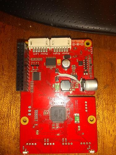
This is what a GoPiGo board looks like from the bottom. At the very top you can see the two large white connectors that the GoPiGo motors connect to, and to the immediate left is the female 26-pin header that fits over the first 26 pins on the GoPiGo when assembled.
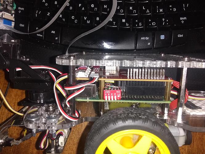
This is a side view of my 'bot showing how the Dexter Industries GoPiGo controller board fits onto the Raspberry Pi below it. Notice how it fits onto the first 26 pins of the Raspberry Pi GPIO connector. The little red dip-switch is something I added that will let me select what operating system to use on-the-fly, and is not part of the stock robot.
The red-white-black three-wire cable is one of two servo cables that plug into three-pin headers for controlling the servos.
Like I said, I don’t have a Brick Pi, (I don’t even have decent pictures of a brick pi!  ), so I’m not the definitive expert.
Hopefully what I have said will help you figure out what you have and how to make it work.
Please don’t forget to reply and let everyone know what happens and how you got things to work - if at all.
Thanks!
 ) and
) and 
