I just want to apologize for not being very clear in my question and I understand what you guys are saying. After reading the guidelines for this site I understand now that this was not the correct format or structure to ask this question, its not that this site can’t give me the information I need, its just that the way I asked was downright terrible and wasn’t facilitating any learning. This site is supposed to be a site of knowledge that could be used by all users in the community, not just for personal use and specific questions especially not for business matters. I have edited my question in what I believe to be a much more “relevant to others” format, that just seeks clarity in fundamental concepts of electricity and magnetism and how they could apply to sensing position/angular rotation of a physical object rather than clarity in the specific operation of a sensor that I haven’t even given you any information on.
Unfortunately I was told explicitly that I cannot say what the function of the sensor is nor what it is called due to confidentiality agreements. So after re-reading my post and the helpful comments of the community I understand the issues with my post and have revised it accordingly.
I really appreciate all the feedback from you guys, this site is an incredible resource, filled with knowledge for all and is filled very intelligent people that are willing to help others. I would love feedback from you guys on the format of my newly edited question, I think I have a much better understanding of the purpose of this site and how to ask questions that not only help me figure out my own problems, but also benefit the community.
Just to clarify some points that I didn’t explain in the original post:
-
I am not asking anyone to figure out the issue we are having with this sensor, I haven’t told you what it is or what its function is, nor any details as to the problem we are having with it. I would love to bring you guys into the problem and have in-depth discussions on possible root causes because I think it would be really cool to see the ideas you generate and I would definitely have a great time talking about it with you guys but again, due to confidentiality agreements I must keep the specific details of the sensor as vague as possible.
-
It’s not that I trust you guys more than the supplier of this part or that I trust the supplier more than you guys or that I don’t trust the supplier at all, it’s just that I am looking for a third party’s explanation of some concepts the sensor uses just to confirm and clarify what the supplier is explaining to me. I am just simply having issues with some concepts they are explaining to me which could very well be completely valid, it’s just that I am not grasping them. So I am looking for a third party that might be willing to help me. But if the supplier is just spoon-feeding me explanations and telling me to believe things that I don’t completely understand I am not just going to believe them just because they say I should. So I apologize for not making these points clear in my original post.
Reformatted Question:
I work for a large car company in North America, and we have a sensor (which unfortunately I can’t go into detail with due to confidentiality agreements) but essentially it is a rotary position sensor that uses two rotating magnets on different teethed gears (like the ones shown in Figure 1) to determine angular rotation of the big wheel (Wheel 1 in Figure 1) from some preset “zero” point. My team is trying to determine the root cause of an issue with this sensor so I talked to the supplier who explained to me how it works and I still don’t completely understand how the sensor works which makes it hard to root cause, so I am hoping someone can give me some theories on how they think a hall effect sensor that uses two magneto resistive pairs that is setup like the one in Figure 1 would be able to tell the vehicle how many degrees the big wheel (Wheel number 1 in Figure 1) has moved.
The supplier of the sensor explained how the sensor works and gave some speculation as to why the issue might be occurring. Regardless of what the sensor specifically does, the image and explanation above just give some context to my specific issue to better illustrate the concepts I am having issues with which is how could two magnets rotating on two different teethed gears be able to tell a computer (The Engine Control Module [ECM] on the vehicle) how far the big wheel (Wheel 1 in Figure 1) has moved.
Essentially the supplier told me that this sensor is using the hall effect to tell the vehicle how far the large wheel (Wheel 1 in Figure 1) rotates, my understanding of a hall effect sensor which is shown in Figure 2 (Which I guess I will put in the comments because I can only put two links in a post) was that the varying magnitude of the magnetic field strength which would come from the magnet physically moving around the big wheel (Wheel 1 in Figure 1) which would correspond to certain amount of degrees of rotation.
So for example if the sensor saw X amount of magnetic field which would increase or decrease as the magnet moved around the big wheel (Wheel 1 in Figure 1) then that would correlate to X degrees of rotation for the big wheel(Wheel 1 in Figure 1). But in this sensor, based on the image given to me by the supplier (Shown in Figure 1) that is not what I think is happening in this sensor.
So I understand now that my original understanding was incorrect, you probably aren’t going to have the magnet physically rotate around the big wheel (Wheel 1 in Figure 1), this wheel is pretty big relatively speaking [Can’t give too much away ;)] so you would need a pretty strong magnet for the sensor to be able to detect the magnetic field if the magnet was all the way on the other side of the big wheel.
So I did some more research and came across another method for how a rotary position sensor could use magnets to determine the angular rotation of the big wheel.
Here is how I now think a rotary magnetic position sensor works:
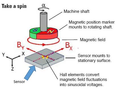
I think that a single rotating magnet attached like the one in Figure 3 will produce magnetic flux which the sensor would somehow convert into sinusoidal voltages (Maybe one of you could explain how that works but that’s for another day) which would correspond to a certain degree of rotation. But again, from the picture the supplier sent me, I don’t think that is going on here either.
So I am just looking for some of your ideas on how a setup like the one in Figure 1 with two rotating magnets on two different teethed gears could tell a computer how far the big wheel has moved. I was thinking there could possibly be something similar to this setup used in another industry application that you guys might know about or if there is a general methodology for how setups like the one in Figure 1 work.
So hopefully I illustrated my question better, (I couldn’t have made it much worse from the original lol) and I really appreciate all the help from this community.