@jimrh When you get your head above water please put some thinking on this:
The GoPiGo3 comes with a (TalentCell 3000mAh) Li-Ion Battery and a 12.6v 1A “smart charger” that contours the charging (current?) according to some algorithm (based on delta-V?). The charger and algorithm are designed to charge the battery with no load.
Dave is “planning” to dock when the battery voltage is low, and get off the dock when the battery is charged if the time-of-day is between 8AM and 10PM (otherwise stays on the dock for a trickle charge).
Issue: Dave presents a mixed load to the battery charger - Battery plus Raspberry Pi 5 plus Pololu 5V 2A supply for the LIDAR and Camera. The LIDAR and Camera are in idle state but are drawing a little and the Pololu step down supply has some conversion loss. As a result the charger never goes into “green” trickle charge mode.
I can nap the Pi5 to a low power state, but interestingly the fan starts up fairly strong, drawing power. I do not have the “enable” wired up for the Pololu supply to put that into a quiescent state when the processor is napping. That is possible, but I think it needs a physical “disable” pull up resistor of some value, and programming a GPIO pin to 0/low to enable the supply.
Charging takes about four hours if the Pi5 is put to nap (4-5W to the processor, 0.5W to the Pololu, and the rest of the charger’s 12W goes to charging the battery.
Isn’t there a BMS (Battey Management System) chip inside the Li-Ion battery that would handle safely charging from a fixed voltage source, such as a 1.5A or 2.0A 12.6v supply? This would give extra power for the battery beyond the RPi, and the Pololu, and would protect the battery should it gets fully charged, No?
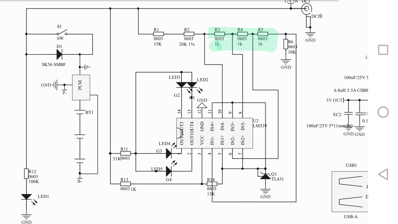
The schematic shows a pcm, but I don’t remember the type nor it’s spec, and it doesn’t have a designation on the schematic.
When I get the chance, I’ll open one up and see what I can find out about the pcm. I’ll have to open up the charger and see how it’s implemented. The fact that they went to the trouble and expense of a special Li-Ion charger makes me believe it’s important.
Perhaps they just re-used the charging board from their NiMH batteries, (that has the wrong current profile), and made up for it with the charger? The fact that the state-of-charge indicator was still calibrated for NiMH batteries leads credence to that possibility.
I would hesitate to just plug in a charger with the wrong charging profile to the battery pack.- especially since flaming robots are high on your “Hell no!” list.
And I was thinking I need to update Carl to Li-Ion…
I think, for Dave, I need to implement controlling the “enable” of the Pololu supply and retest napping the Pi5. That should take the non-battery load to a few milliamps.
The ENABLE logic:
The regulator is enabled by default: a 100 kΩ pull-up resistor on the board
connects the ENABLE pin to reverse-protected VIN. The ENABLE pin can be
driven low (under 0.7 V) to put the board into a low-power state.
The quiescent current draw in this sleep mode is dominated by the current
in the pull-up resistor from ENABLE to VIN and by the reverse-voltage protection circuit,
which will draw between 10 μA and 20 μA per volt on VIN when ENABLE is held low
(e.g. approximately 30 μA with 3 V in and 500 μA with 30 V in).
If you do not need this feature, you should leave the ENABLE pin disconnected.
So what kind of circuit can change this “enabled by default” to “disabled by default”? They suggest something called “open drain”?
Great idea…BUT I have enough trouble lining up two robot contacts with two spring loaded iRobot dock contacts, no way I have the mechanical skill for that.
I need a circuit:
Pi Off, GPIO pin floats - pull enable low,
Pi GPIO pin active {high/low}?: float or set enable high (higher than 0.7 v up to VIN allowed)
The circuit you are talking about would be a level-shifter and a MOSFET would work as a pull-down except for one problem:
Once the pi goes to sleep the pin’s no longer under your control and it will likely become undefined.
Also, a MOSFET is usually active-high. Even if you use a P-junction MOSFET, (active low), you still need a pull-up to V3v to provide the necessary voltage differential so that it totally pinches off when inactive.
You need:
Something that is absolutely guaranteed to work, come hell or high-water.
Something simple enough to be “idiot robot” proof and guarantee functionality.
First Idea:
A third contact immediately adjacent to the ground contact on the charging dock. You could even make the existing contact wider.
You then add a separate contact immediately next to the existing ground contact but separated by about 1/16"
Result:
Whenever Dave/Carl docks the boost enable line is automatically pulled low disabling the boost supply. Undocking automatically re-enables the boost supply.
Second idea:
Mount a small microswitch or push-button underneith the ground contact on the robot, such that when the robot docks and the contact flexes, it activates the button/microswitch.
The best way would be to arrange a normally closed switch wired to “pull-high” when closed.
Third idea:
Mount a normally open reed switch on the bottom of the robot somewhere. Then mount a tiny but powerful magnet on the base near the reed switch so that the magnet activates the reed switch. You might be able to cheap-out by using an actuator magnet from an old hard-drive.
You really don’t want to get involved with complicated circuits when a simple solution will work wonderfully.
One other option is to find a GPIO signal that’s asserted whenever the GoPiGo robot is running and de-asserts when the robot turns off. It would depend on if the assertion is active high or low, but something could be worked out - I may need something like that for my robot to shut-down the boost +5 when my robot turns off. However, it would be more complicated and would require you to build a small circuit board with several components on it.
If the Enable has a 100k ohm pull up to VIN of 9.6 to 12.6 volts, wouldn’t a 2k pull-down make a voltage divider that puts less than 0.7 volts (reliably) to the Enable (and the GPIO pin) when the GPIO pin is not powered, and 3.3v (minus the pull-down potential which is less than 0.7v making it 2.6v or more) to the Enable when the GPIO pin is set high?
What is the minimum voltage that it will sense “high” on?
Isn’t that pin a low enable?
If I’m not mistaken, the enable pin on that beastie essentially drives a MOSFET gate, drawing squat-doodle current so you might very well be able to drive it directly from the Raspberry Pi. Though I’d look at the data sheet to see what the current draw for the various states is, though if I remember correctly, someone said that this beastie is pulled high by a ±10kΩ resistor, so I doubt that thing pulls any current to speak of.