Without “Test” robots are doomed to be stranded and helpless in their moment of need.
I have been testing Carl’s self management of battery charge state for almost two weeks now. He keeps going longer without assistance, but again today after two and half days, he got into a bad situation.
When he docked for a charge, his “Smart Charger” went into trickle charge mode instead of the full charging mode that Carl expects. Carl has difficulty differentiating trickle charging from the real charging mode, and this particular time expecting charge mode, he sat on the dock thinking his life is good while not noticing his battery voltage was not going up.
I had to add another rule to protect Carl:
if DOCKED for longer than 7 minutes,
and CHARGING,
and meanBatteryVoltage is (still) below the “8.5v need charging threshold”
there is a problem - get off the dock and try again.
Carl has to get smarter than his sometimes dumb “smart charger.”
Ouch - a missing rule. The only time he asks for manual help is if the distance sensor says the wall behind the dock is not there, or something is blocking him from turning around to see if the wall is there.
In fact, last night, he started a new behavior - twice in a row, he thought his docking had failed due to not recognizing that he was indeed charging. Twice he got off from perfectly good dockings to “try again”. Luckily the third time was a charm, and he recognized the charging state after docking.
Another important consideration is contact resistance since so-called smart chargers rely on the battery’s current profile to know where it is in the charging cycle - they expect the battery to draw less current as the percentage of charge increases. Poor contact, (higher than normal contact resistance), can fool the charger into thinking that Carl’s batteries are more fully charged than they are.
Real “smart chargers” use one or more signalling leads, (in addition to the power leads), to communicate with on board / in-battery controllers that can determine both level of charge and degree of charge balance for all the batteries in the device.
When Carl backs onto the dock and I see the charger indicator change to solid red.
Carl always “speaks his mind”. He said “Docking Failure Possible, undocking”
Then he announced “Time to get on the pot” and tried again.
(From the log I can see the short mean voltage is higher than the long mean, and the dead give away that the charging was successful is the short peak at 10.5 volts. Also the plot from RPI-Monitor shows charging had started but he got off.)
**** Docking Failure Possible, undocking

Juicer Values:
Juicer Run Time 1 days 22h 49m
lastReading 8.669 volts
shortPeakVolts 10.554 volts
shortMeanVolts 8.065 volts
shortMinVolts  7.761 volts
longPeakVolts  9.251 volts
longMeanVolts  8.030 volts
longMinVolts   7.821 volts
Charging Status:  Not Charging
Last Changed: 0 days 3h 24m 3s
Last Change Rule:  310c
Docking Status:  Docked
Docking Count:  778
Last Docking Change: 0h 5m 3s
Play Time Limit 8.1v

**** INITIATING DISMOUNT ****
**** Dismounting
*** chargingState changed from:  Not Charging  to:  Not Charging  ****
*** by Rule:  310c
**** DISMOUNT COMPLETE AT  2020-01-26 17:50:20
---- Dismount 778 at 7.9 v after 0.1 h recharge

**** Time to get on the pot
**** Turning around to be at approach point

**** DOCKING REQUESTED ****
**** Current  Distance is 261.4 mm 10.29 in
**** Approach Distance is 263.00 mm

**** INITIATING DOCK MOUNTING SEQUENCE ****
**** TURNING 180
**** Preparing to Back onto dock
**** BACKING ONTO DOCK -82 mm
**** Backing for a bit to account for measurement errors
**** Backing again just to be sure we're good
**** DOCKING COMPLETE AT  2020-01-26 17:51:04
Everything fools this charger. First it uses the sensed voltage to guess if the pack is a nominal 7.2v, 9.6v, … (5S-10S cell NiMH/NiCd battery pack). Then it tries some quick pulses of various voltages and currents to determine something, then it starts charging and then stops to measure the actual battery voltage and the slope of the voltage over time, and who knows what else it pulls out from under the kitchen sink to try on the battery.
Mean while the Raspberry Pi time slices present a varying load which causes the battery voltage to be jumping around while the charger is sniffing all this.
Carl is running an “I’m watching you” strategy to try to out-smart the smart charger, but he can only see the battery voltage, and cannot check too often or the load will make the charger think the battery pack has peaked and it will switch to trickle charging. Two dim wits playing cards in the dark.
Well, yeah - if I could get Carl to dock with a DB25 connector or something. I’m feel lucky every time he gets the two mated.
When I said Carl speaks his mind, you have to imagine my wife in the office where Carl is, announcing to me (in the other room watching our democracy in the toilet) “Carl’s saying something!” She has trouble understanding Carl’s text-to-speech. She likes his voice, but doesn’t understand what he says very well.
Have you considered a 16uf silver-tantlium capacitor across Carl’s charging contact leads where they connect to the PC board? This will help suppress voltage spikes and high frequency impulse noise that can confuse connected circuitry.
The addition of a 0.01uf capacitor across the same leads will bypass higher frequency noise as well.
Have you measured the voltage drop across various segments of the power supply wiring?
a. Using the mA scale on a DVM, measure the drop across both positive and negative circuits, end-to-end. (Starting at the GPG’s power socket on the PCB and terminate as close to the charger as you can. If you have reasonable access to the source pads on the power supply’s circuit board, measure there.)
b. You should get virtually no reading at all. If you get anything greater than a mV or so, measure smaller and smaller segments of the offending lead until you find the poor contact and try to improve it.
c. Any impedance at all can build up significant noise.
How do you know that there is all this voltage variation? Did you measure with a 'scope? A DVM?
What is the absolute maximum surge current draw?
I note that you don’t have any filter inductors either.
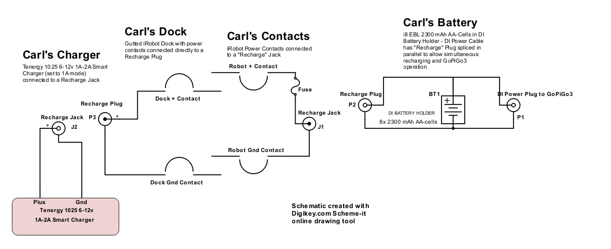
Based on your schematic I would install the capacitors across the power connector on the GPG board and install a bifliar wound toroidal inductor - a couple of henries max - that can handle the peak charge current in the leads from the GPG to the batteries. You can experiment with the inductance, start with a few hundred mH, and go up from there if you need to.
a. A “bifliar” winding is two pieces of wire wrapped around the core laying together, side-by-side, as if they were one wire.
b. You connect the positive circuit through one of the wires and the negative circuit throu the other.
c. You can look up “power supply filter inductors” on DigiKey or Mouser.
The bottom line is to:
First look for any significant voltage drops and eliminate them.
Measure and quantify the noise problem.
Add filter capacitors across the power connector on the GPG board.
Then add filter inductance in the power leads if needed.