TalentCell YS1203000 "State of charge" monitor

I have decided to break out the discussion of the TalentCell “state-of-charge” indicator from the rest of the battery discussions.

Summary:

Though the TalentCell battery appears to be a Thing of Beauty, the state-of-charge indication is more like a Thing of Gagh!

Due to @cyclicalobsessive and @KeithW’s exhaustive research on the battery’s runtime and voltage cut-off limits, I was able to make some significant progress today.

First of all:

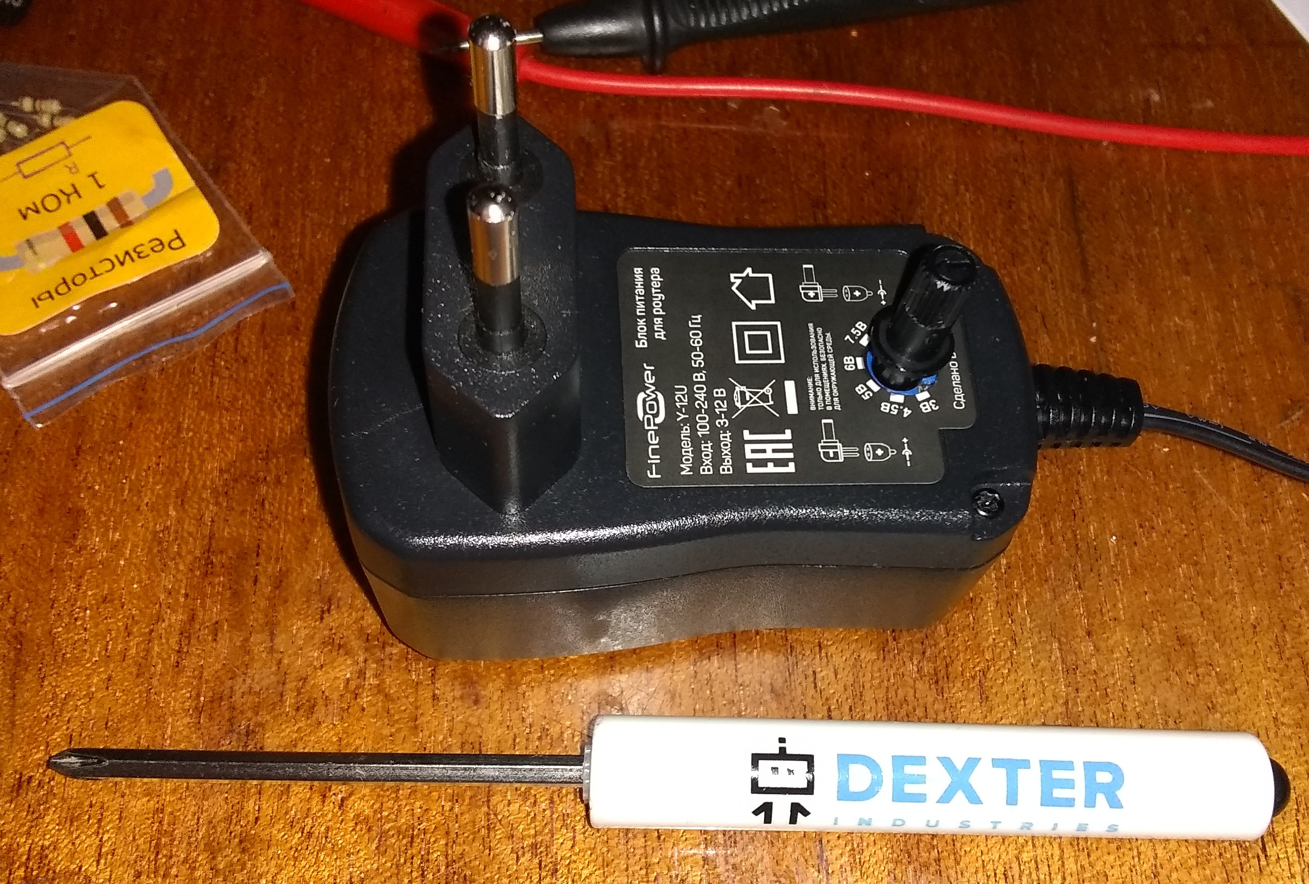
  1. A fully charged YS1203000, fresh off the charger reads 12.47 v on my inexpensive meter. (Assuming full charge voltage is 12.5v.)

  2. @cyclicalobsessive’s drop-dead voltage is 9.75v

  3. This gives a voltage delta of 2.75v (assuming 2.8)

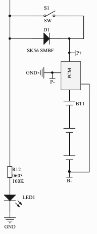
  4. I discovered the following schematic for a four-LED voltage monitor at https://mechatrofice.com/circuits/voltage-level-indicator-circuit

LED-voltage-level-indicator-circuit-diagram-1

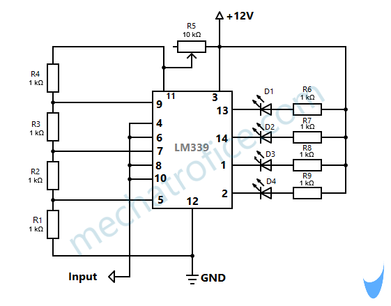
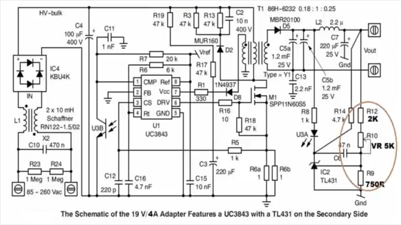
Additionally, they appear to be using a TL431 programmable voltage reference in the circuit.

Update:
(Special reference to @cleoqc)

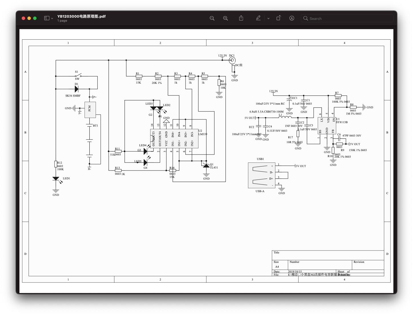
I sent TalentCell a request for the power monitor PCB schematic.

They responded with this:

YB1203000电路原理图.pdf.txt (54.0 KB)

What is significant about this circuit is their use of a TL431 programmable reference diode, so it might be possible to:

  1. Change the voltage on the reference lead of the diode to make the meter reading more accurate.

  2. Suggest differing voltages so that the same circuit can be used with different battery technologies.

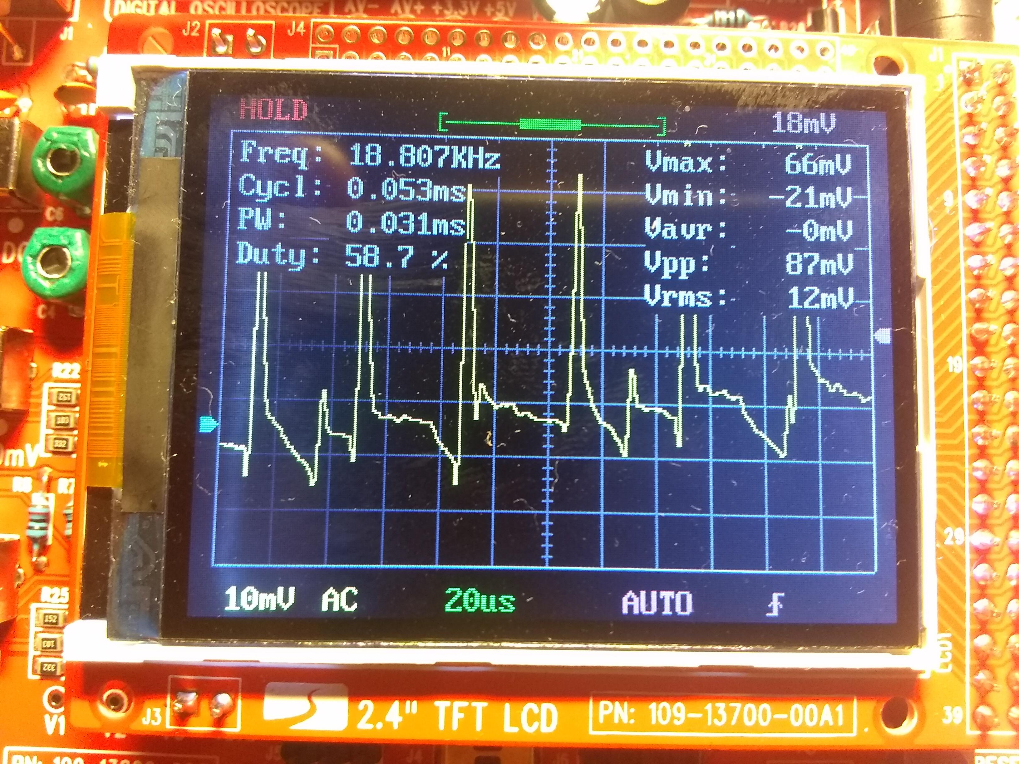
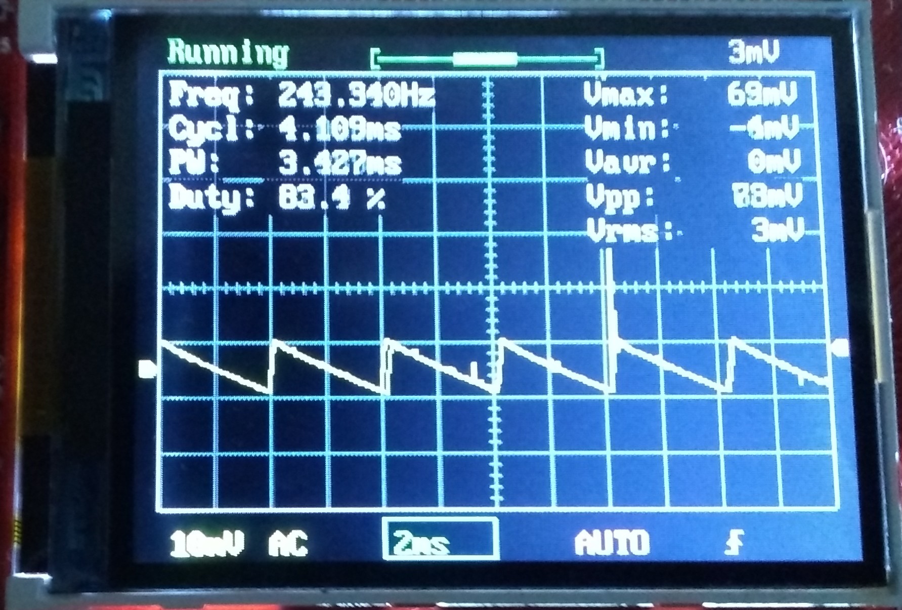
I have also asked for the circuit for the charge controller board as I am thinking of adding an inductor, (and possibly a capacitor), to filter out the high-frequency regulator noise.

2 Likes

An initial examination of the state of charge monitor shows an apparent design defect

The input voltage is connected to the circuit’s reference resistor ladder network and the reference voltage is being applied to all the other comparitor pins as a common voltage.

This is exactly backwards compared to the reference circuit shown above.

The reference voltage should be across the standard reference voltage to maintain a fixed reference ratio for all the comparitors, and the input voltage should be attached to the common inputs.

As it is, it cannot accurately measure the voltage as the voltage across the resistor network, (and hence the point where the LEDs change state), is constantly varying, rendering the LED readings essentially useless.

1 Like

9.75v is a chosen “get to the juice-bar looking fit” voltage (~15 minutes before “drop-dead”)
8.1-8.4v was the “drop-dead” voltage.

“Full-Charge” if you leave the pack charging after the green light first appears will eventually be between 12.4 and 12.6v, depending on when it is disconnected. There seems to be a “trickle-charge” phase that repeatedly cycles between a low of 12.46v at 130mA charge rate and a brief high of 12.6v at 30mA.

(BTW, I have characterized my GoPiGo3 readings to result in “computed battery voltage” that averages to within the 0.01v difference of readings on three different voltmeters. Individual “computed battery voltage” is within a 2-sigma deviation of +/- 0.04v, and a 3-sigma deviation of +/- 0.07v - which is to say I believe ROSbot’s “battery voltage” is +/- 0.05v most of the time, and my three digital voltmeters turned out surprisingly consistent. )

On the following test session, (which began immediately after removal from charging), the “under-load” voltage initially read 12.58v at ~0.400A on my in-line meter. (The voltage was solid with the load bouncing -50mA to +150mA.) The meter voltage continued to read 12.58v one minute after the switch was turned on, and ROSbot computed 12.58v from the GoPiGo3 reading:

2021-06-19 20:03|------------ boot ------------
2021-06-19 20:03|Current Battery 12.58v EasyGoPiGo3 Reading 11.77v

This morning the under-load starting voltage was only 12.23v (+/-0.05) because I forgot to look at the in-line meter:

2021-06-21 07:12|------------ boot ------------
2021-06-21 07:12|Current Battery 12.23v EasyGoPiGo3 Reading 11.42v

In the bland delivery of Pete Davidson: OK.

2 Likes

And that’s why I chose your voltage as what I called the “drop-dead” (allowable minimum), voltage, to allow the user to recover the robot (if necessary), do a controlled shutdown, and get a fresh battery.

I feel it’s a piss-poor design practice to give the user a low-voltage warning mere seconds before the robot is violently powered off.

So, I want the users to be able to “get to the juice bar”, (gotta love the choice of words! :wink: ), with the wheels still spinning since people might not be using the relatively robust power monitoring software you use.

P.S.
The last LED in the stack is NOT controlled, but merely acts as a power-applied indicator.

P.P.S.

I may end up dropping the allowable minimum to 9.5 so the values work out evenly as 5% resistors

And yes, the State-of-Charge monitor is wired exactly upside-down, (that is, backwards with respect to inputs and reference voltage inputs). To correct it would require cutting and jumpering something like 12 traces or a complete PCB redesign for that circuit.

I’m going to try to figure out a way to do a simple single, (or two), cuts and jumpers repair. Not sure if it’s even possible.

1 Like

Why does it matter if the reference is IN1+ against output on IN1- or the reverse? Doesn’t it just change the level of the result to 0 or 1? Could it be it was more convenient to direct wire the output to the led using the “exactly upside-down” as an inverter?

UPDATE: Ok, I get what you are saying - to work what they wired the resister values are different if the ladder is on the input side from when on the reference side?

Since the discharge curve is no linear, the resistors would already be custom values, just different if on the input side,no?

2 Likes

Black tape and software?

That would still provide about 7 minutes reserve

2 Likes

YB01203000_BMS

If that schematic matches the PC board, their BMS scares me - there are no connections to the individual cells!

2 Likes

No, that’s the chip manufacturers “reference” circuit. The TalentCell version has taps at each battery.

I’ve asked to see their schematic, but so far, no banana.

On a different front, I’ve been trying to come up with a modification to the original circuit that would require a minimum of part changes and a minimum of “cuts and jumpers”.

Ideally, TalentCell should correct their battery meter, though I’m not holding my breath.

Either I’m suffering from a bad case of “brain fog” or I’m just going totally senile as I’m having the Devil’s own time figuring out the resistor ladder network values.
:crazy_face:

This should be trivial.

Sheesh!

2 Likes

Update:

I’ve been working on cobbling up a reasonably beefy “adjustable lab power supply” to test modifications to the state of charge controller circuit - I need to be able to vary from about 14 volts down to about 7 or so.

I decided that a couple/few hundred dollars for a balls-to-the-walls bench supply is a bit rich. So, I’ve decided to take a “Universal Laptop Power Supply” and modify it into a zero to thirty volt supply and use that for testing.

  1. Laptop power supplies have to have reasonable regulation and minimal noise to be useful.
  2. A 60-75 watt supply should be adequate for most anything I want to do.
  3. $30 is a lot easier for me to swallow.

More later.

2 Likes

Part of the problem is getting the feedback divider network ratios correct. I need a specific range of voltages, but I have to be careful not to allow the outputs to get too high as it can damage, (as in “explode”), internal components.

It turns out I have two supplies, by the same manufacturer, using essentially the same circuit, with voltage ranges covering the entire range I want to use. (3-12v and 9-24v)

With this, I can see the different values for the divider network and combine them.

I also found a reference schematic that’s not exactly the same, but close enough.

R12, R10, and R9, (circled), is the feedback/voltage setting network I need to study and modify.

Of course the laptop supply is a bit more sophisticated because of the extra filtering, higher current and tighter regulation, but as this, [the schematic], is almost exactly the same as the smaller supply, and substantially similar to the larger one, it’s a great help getting me oriented.

Additionally, this circuit also uses the Ti431 programmable reference in a way very similar to the state of charge meter itself, so it will provide valuable information there too.

With all this, I should be on the home stretch.

More later.

2 Likes

Update:

First, I have learned that trying to create a 3v to 30v variable supply from a laptop power brick is not reasonably possible.

  1. This has been a real crash-course in switch mode power supplies and I have learned a lot.
  2. There are a number of things that affect the range of voltages available:
    • Power, (amperage), required.
    • Lowest voltage and voltage range.
    • Type of switch mode chip being used, which feeds directly into. . .
    • The sophistication, and hence the cost, of the final product.
       

This manufacturer, (FinePower, from China), makes two models:

  • A 3v - 12v “Battery Eliminator” adjustable supply.
  • A 12v - 24 “Universal Laptop” adjustable supply.
  • All voltages are selected by a seven-position rotary switch which selects individual parts of a resistor network.
     

The laptop supply has an experimentally derived range of 7.5v - 50+v. (At 50v, some of the “magic smoke” :wink: was beginning to escape, so I stopped the test.)

The battery eliminator supply has a derived range of about 2v to at least 15v, but I did not want to blow up the filters so I stopped.

Though both supplies used essentially the same circuit, there were differences:

  • The laptop supply had a beefier transformer, able to handle larger amounts of power.
  • Components, especially those on the high-voltage side of the controller, are optimised for low ripple and high voltage.
  • It also invested more money into regulation and filtering throughout the design.
  • By comparison, the “battery eliminator” was a cheaper design, with a smaller transformer that makes filtering more difficult.
  • It lacked a lot of the secondary-side filtering the laptop supply had.
     

Both do their job, and I will probably get another of the cheap ones to test the battery meter with.

One thing I will have to do is reduce the power supply noise of the cheaper supply if I am going to use it for anything serious.

Viz.:

Notice there is a lot of digital switching noise, 19khz and at least 87mv of this high-frequency noise that had a lower frequency ripple, (about 50-60 hz, which is the regulator ripple), superimposed on it.

The laptop supply, by comparison, had a 25mv, 60hz sawtooth, (regulator ripple), just before the final output filter and no high-frequency switching noise.

If I get another of the cheap battery eliminator supplies, a toroidal filter inductor and possibly a couple of capacitors should filter that noise out nicely.

2 Likes

One thing I forgot to mention is that the complexity of the switching supply’s design is directly proportional to the range of voltages to be covered.

A supply designed for a single voltage can be carefully optimised for that specific, individual, voltage. Ripple can be more easily filtered and it can be quite stable.

A small range of voltages makes things a bit more complex, but not too much. It doesn’t matter what the small range is, the requirement is a relatively small range.

A larger range requires a particularly specific design, specially designed transformers for energy storage, and components surrounding the controller IC that will allow a vastly greater range. The IC is also specially designed for that use and is more expensive.

Another interesting fact is that the transformers in switching supplies are not used for “transformer action”, (converting one voltage to another), but as energy storage devices. They store the pulse of power provided by the controller and supply it as a burst of energy to be used on the output side. Note that DC/DC voltage supplies don’t use transformers, but single winding inductors instead as the energy storage device.

The transformer is used to provide voltage isolation between the high voltage mains power side and the lower voltage output side. This component becomes especially more complicated and expensive as the voltage range increases.

The overall result is that a power supply designed for a particular range of voltages is difficult to modify to provide a completely different range without extensive redesign.

1 Like

That would seem to make sense - you wouldn’t want a lot of electrical noise for a laptop, whereas for a less sophisticated device where you’d use a batter eliminator it might not make as much difference. Maybe?

I’m guessing this is for an AC circuit? My knowledge of electronics is pretty much limited to basic DC circuits.

/K

2 Likes

No. The world used to be ruled by analog hardware “wizards”. The digital hardware guys took over and chopped everything up into discrete “digital” moments and left it to a few remaining analog guys to put their moments back together into linear streams without “singularities”.

2 Likes

@cyclicalobsessive is almost correct.

In this case it starts as mains power and is rectified into DC using a full-wave bridge and a MONSTER filter capacitor to make almost pure DC.

Then, as cyclicalobsessive so rightly observed, it is chopped up, (in a PWM/frequency domain kind of way), to store a specific amount of energy in an inductor. Once the energy is released, it is rectified, filtered, sampled by the feedback circuit, and presented to the output terminals.

Depending on the voltage present at the feedback circuit, the controller stores proportionally more or less energy in the inductor.

The specific circuits I’ve shown here are relatively simple. The controller runs until the voltage reaches a certain value, then it stops. At this point the voltage drops rapidly until it drops below some minimum value, then the controller starts pumping energy into the inductor again and it slowly builds to cut-off and the cycle starts again. Just like a charge pump or a blocking oscillator using a wave forming capacitor/resistor network. Ergo, a sawtooth wave for the regulator ripple.

Cyclicalobsessive, I have found that in many ways, (especially in power electronics, and audio amplifiers are essentially a subset of this), everything you learned in analog power still applies, just the ripple frequencies are higher.

All your AC theory still applies, (Yes Virginia, there is a cosθ), and all the special considerations for dealing with AC still apply.

The big difference between an “analog” power supply and a “digital” supply is in the way voltage transformation and regulation is achieved.

In an analog supply, (think 7805 regulator), it is essentially a high-power automatically variable resistor, automatically changing the amount of power dropped to give the correct voltage. The excess power is dissapated as heat and therefore wasted. (That is, unless you’re using it to heat your computer room!)

A digital supply does the same thing, except for dissipating the excess power across a resistance, it sends “bursts” of power, just enough so that when it is filtered it is the voltage/current you need with minimal heat generated. Ergo the efficiency is much higher.

2 Likes

I would disagree, at least to an extent.

IMHO “digital” electronics is an extension of analog electronics. You could also say that analog electronics is a special case of digital electronics where the clock speeds are too fast to perceive. (Can you say “Quantum Mechanics”?) Maxwell had a lot of this totally knocked long before DeForest invented the triode tube.

The switching power supplies of today are almost exactly identical to the “boost” and “flyback” power supply circuits that were used in CRT TV’s and monitors in days gone by.

This huge inductive “kick” in voltage caused by the rapidly collapsing magnetic field was used to create the almost 500 volt “B+ boost” from the 200 or so volt B+ voltage generated by the power transformer, in exactly the same way a modern switching supply can generate a larger DC voltage from a smaller one. Even the switching frequency is almost exactly the same since TV’s in the US were locked to the 15,750 Hz horizontal sync frequency, and instead of a power MOS-FET transistor, a 6BE6/12BE6 beam-power tube was used to handle the large amounts of current required.

That same inductive “kick”, (pulse), was also used by an extra zillion-or-so turn winding on the horizontal output transformer to produce the 15 to 30 kv needed for the picture tube.

Most of the charge controller ICs and circuits of today are simply miniaturized versions of the blocking oscillators and phase correction circuits used back then.

It’s all old news in new clothing.

2 Likes

Update:

A major milestone has been met!

I finally cobbled together a 2 - 30v variable supply using the battery eliminator.

I bought an extra one, as I use it to power the el-cheapo 'scope I bought and this is what it looks like unmodified.

I did some research and calculations and discovered that I had the necessary parts in stock. :+1:

I removed the rotary selector switch and replaced it with a 10k pot and a 1k resistor.

Here you can see the pot and the new 1k resistor next to it.

I also replaced the final filter capacitor with a 1000μf filter.

You can see it in the lower center. The circular ring of holes were for the rotary switch.

Here is what it looks like assembled.
(Luckily, all the modifications still fit in the original case.)

I discovered a flaw in the way I was measuring the ripple and I was inadvertently introducing a lot of noise that really wasn’t there. (And substituting the larger capacitor wasn’t even necessary!)

Here’s what the (unloaded) output look like.

A much more respectable 10mV of sawtooth regulator ripple with the occasional spike that I have no idea where it comes from.

Next steps:

Build up the state of charge meter on some proto-board and try out some of the changes I have in mind.

I’m psyched!

:grin:

2 Likes

Wow - that’s super impressive. Even moreso that you had everything you needed in stock.
/K

2 Likes

I had just stopped off at Chip & Dip a few days ago and had dropped a few thousand rubles on a bunch of boxes of assorted resistors. (I need a decent assortment of parts if I’m going to do any kind of serious hardware hacking and the few grand was a worthwhile investment into my parts inventory.)

However, all is not sweetness and light.

I discovered that all the useable voltage values were at one end of the adjustment, from about 50% and above, making adjustments extremely difficult.

After puzzling and puzzling until my puzzler was sore, :wink:, I had one of those “Doh!” moments. :crazy_face: :roll_eyes:

The adjustment resistor was twice the needed value! That’s why all the readings were in the top half. . . .

And I didn’t have the correct value.

Today I went back. Got the correct value, some solder-wick, (I was out of it), and the LM139 I will need to prototype a corrected meter circuit.

Tried again.

The readings are now more spread out, but are still bunched at the high end, just not so badly.

Obviously, the voltage reference diode isn’t linear and I’ll need a reverse log taper on the adjustment control. Since this part is, essentially, impossible to get unless you’re ordering fifty zillion as a special order, I had the following choices:

  1. Stop effing around, bite the bullet and drop about $200 on a real lab supply.
  2. Go crazy trying to find an unavailable part.
  3. Get a “digital potentiometer” chip, program and upload a 5k reverse-log taper, and install it.
  4. Throw my hands up in despair and give up.
  5. Suck it up, count my blessings that I finally got SOMETHING that I might be able to work with, and move on.

I’m going with #5 for as long as I can.

We’ll see.

2 Likes

You also have several batteries that you can discharge to a set of desired voltages for testing.

2 Likes