TalentCell YS1203000 "State of charge" monitor

One thing I forgot to mention is that the complexity of the switching supply’s design is directly proportional to the range of voltages to be covered.

A supply designed for a single voltage can be carefully optimised for that specific, individual, voltage. Ripple can be more easily filtered and it can be quite stable.

A small range of voltages makes things a bit more complex, but not too much. It doesn’t matter what the small range is, the requirement is a relatively small range.

A larger range requires a particularly specific design, specially designed transformers for energy storage, and components surrounding the controller IC that will allow a vastly greater range. The IC is also specially designed for that use and is more expensive.

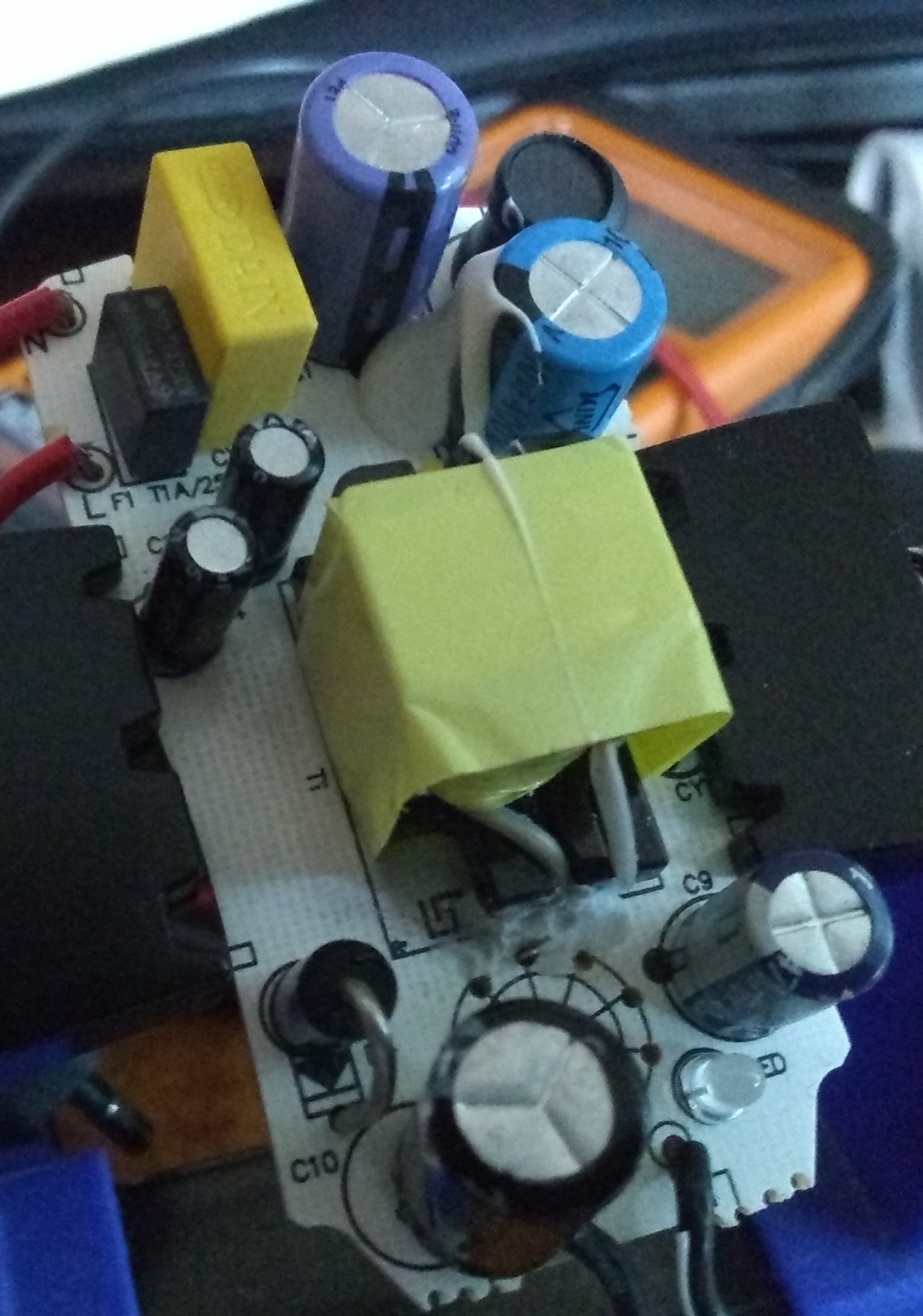
Another interesting fact is that the transformers in switching supplies are not used for “transformer action”, (converting one voltage to another), but as energy storage devices. They store the pulse of power provided by the controller and supply it as a burst of energy to be used on the output side. Note that DC/DC voltage supplies don’t use transformers, but single winding inductors instead as the energy storage device.

The transformer is used to provide voltage isolation between the high voltage mains power side and the lower voltage output side. This component becomes especially more complicated and expensive as the voltage range increases.

The overall result is that a power supply designed for a particular range of voltages is difficult to modify to provide a completely different range without extensive redesign.

1 Like

That would seem to make sense - you wouldn’t want a lot of electrical noise for a laptop, whereas for a less sophisticated device where you’d use a batter eliminator it might not make as much difference. Maybe?

I’m guessing this is for an AC circuit? My knowledge of electronics is pretty much limited to basic DC circuits.

/K

2 Likes

No. The world used to be ruled by analog hardware “wizards”. The digital hardware guys took over and chopped everything up into discrete “digital” moments and left it to a few remaining analog guys to put their moments back together into linear streams without “singularities”.

2 Likes

@cyclicalobsessive is almost correct.

In this case it starts as mains power and is rectified into DC using a full-wave bridge and a MONSTER filter capacitor to make almost pure DC.

Then, as cyclicalobsessive so rightly observed, it is chopped up, (in a PWM/frequency domain kind of way), to store a specific amount of energy in an inductor. Once the energy is released, it is rectified, filtered, sampled by the feedback circuit, and presented to the output terminals.

Depending on the voltage present at the feedback circuit, the controller stores proportionally more or less energy in the inductor.

The specific circuits I’ve shown here are relatively simple. The controller runs until the voltage reaches a certain value, then it stops. At this point the voltage drops rapidly until it drops below some minimum value, then the controller starts pumping energy into the inductor again and it slowly builds to cut-off and the cycle starts again. Just like a charge pump or a blocking oscillator using a wave forming capacitor/resistor network. Ergo, a sawtooth wave for the regulator ripple.

Cyclicalobsessive, I have found that in many ways, (especially in power electronics, and audio amplifiers are essentially a subset of this), everything you learned in analog power still applies, just the ripple frequencies are higher.

All your AC theory still applies, (Yes Virginia, there is a cosθ), and all the special considerations for dealing with AC still apply.

The big difference between an “analog” power supply and a “digital” supply is in the way voltage transformation and regulation is achieved.

In an analog supply, (think 7805 regulator), it is essentially a high-power automatically variable resistor, automatically changing the amount of power dropped to give the correct voltage. The excess power is dissapated as heat and therefore wasted. (That is, unless you’re using it to heat your computer room!)

A digital supply does the same thing, except for dissipating the excess power across a resistance, it sends “bursts” of power, just enough so that when it is filtered it is the voltage/current you need with minimal heat generated. Ergo the efficiency is much higher.

2 Likes

I would disagree, at least to an extent.

IMHO “digital” electronics is an extension of analog electronics. You could also say that analog electronics is a special case of digital electronics where the clock speeds are too fast to perceive. (Can you say “Quantum Mechanics”?) Maxwell had a lot of this totally knocked long before DeForest invented the triode tube.

The switching power supplies of today are almost exactly identical to the “boost” and “flyback” power supply circuits that were used in CRT TV’s and monitors in days gone by.

This huge inductive “kick” in voltage caused by the rapidly collapsing magnetic field was used to create the almost 500 volt “B+ boost” from the 200 or so volt B+ voltage generated by the power transformer, in exactly the same way a modern switching supply can generate a larger DC voltage from a smaller one. Even the switching frequency is almost exactly the same since TV’s in the US were locked to the 15,750 Hz horizontal sync frequency, and instead of a power MOS-FET transistor, a 6BE6/12BE6 beam-power tube was used to handle the large amounts of current required.

That same inductive “kick”, (pulse), was also used by an extra zillion-or-so turn winding on the horizontal output transformer to produce the 15 to 30 kv needed for the picture tube.

Most of the charge controller ICs and circuits of today are simply miniaturized versions of the blocking oscillators and phase correction circuits used back then.

It’s all old news in new clothing.

2 Likes

Update:

A major milestone has been met!

I finally cobbled together a 2 - 30v variable supply using the battery eliminator.

I bought an extra one, as I use it to power the el-cheapo 'scope I bought and this is what it looks like unmodified.

I did some research and calculations and discovered that I had the necessary parts in stock. :+1:

I removed the rotary selector switch and replaced it with a 10k pot and a 1k resistor.

Here you can see the pot and the new 1k resistor next to it.

I also replaced the final filter capacitor with a 1000μf filter.

You can see it in the lower center. The circular ring of holes were for the rotary switch.

Here is what it looks like assembled.
(Luckily, all the modifications still fit in the original case.)

I discovered a flaw in the way I was measuring the ripple and I was inadvertently introducing a lot of noise that really wasn’t there. (And substituting the larger capacitor wasn’t even necessary!)

Here’s what the (unloaded) output look like.

A much more respectable 10mV of sawtooth regulator ripple with the occasional spike that I have no idea where it comes from.

Next steps:

Build up the state of charge meter on some proto-board and try out some of the changes I have in mind.

I’m psyched!

:grin:

2 Likes

Wow - that’s super impressive. Even moreso that you had everything you needed in stock.
/K

2 Likes

I had just stopped off at Chip & Dip a few days ago and had dropped a few thousand rubles on a bunch of boxes of assorted resistors. (I need a decent assortment of parts if I’m going to do any kind of serious hardware hacking and the few grand was a worthwhile investment into my parts inventory.)

However, all is not sweetness and light.

I discovered that all the useable voltage values were at one end of the adjustment, from about 50% and above, making adjustments extremely difficult.

After puzzling and puzzling until my puzzler was sore, :wink:, I had one of those “Doh!” moments. :crazy_face: :roll_eyes:

The adjustment resistor was twice the needed value! That’s why all the readings were in the top half. . . .

And I didn’t have the correct value.

Today I went back. Got the correct value, some solder-wick, (I was out of it), and the LM139 I will need to prototype a corrected meter circuit.

Tried again.

The readings are now more spread out, but are still bunched at the high end, just not so badly.

Obviously, the voltage reference diode isn’t linear and I’ll need a reverse log taper on the adjustment control. Since this part is, essentially, impossible to get unless you’re ordering fifty zillion as a special order, I had the following choices:

  1. Stop effing around, bite the bullet and drop about $200 on a real lab supply.
  2. Go crazy trying to find an unavailable part.
  3. Get a “digital potentiometer” chip, program and upload a 5k reverse-log taper, and install it.
  4. Throw my hands up in despair and give up.
  5. Suck it up, count my blessings that I finally got SOMETHING that I might be able to work with, and move on.

I’m going with #5 for as long as I can.

We’ll see.

2 Likes

You also have several batteries that you can discharge to a set of desired voltages for testing.

2 Likes

Sounds way more impressive than “forty bucks” :grinning: – but even that would be a LOT of resistors.

#5 sounds like the rational approach.
/K

1 Like

When digital watches first came out, everyone said that watches with hands, (analog watches), were dead-meat.

It turns out that “analog” displays outsell digital displays.

Why?

People usually don’t want to know what time it is, but what time it’s near. “Almost 4:30” makes more sense to most people than 4:27:02.

It’s the same with comparitor circuits.

Aside from the obvious difficulty of getting dozens of batteries charged to exact and precise voltages, (to something like 0.01v), and having them remain stable, there is the problem of varying the voltage across the switching point in each direction.

In other words, the voltage I’m near may be more important than the voltage I’m at.
:wink:

1 Like

Obviously a continuously variable supply is a much better test setup, I was just pointing out a #6 option of testing the circuit in-situ on Charlie exists, and reading out the voltage you are near in software with Charlie.volt()+0.7 or what ever your “voltage_at_battery” correction factor measures to be.

(OK I was being a smart-aleck … )

2 Likes

If it is really possible to use Charlie as a programmable variable power supply, preferably with a 13v to 7v range, I am all ears! :ear:

I will kick myself all the way to Charing Cross in London, worship at your feet, and gladly acknowledge you 20,000 times as smart as I will ever be - if you can show me how to do it with existing hardware.

And I will feel like a total idiot for banging my head trying to implement something that’s already in my pocket.

2 Likes

Ok now let’s not get all semantic about what I was suggesting - a battery is a continuously “varying” power supply, not continuously “variable”.

Now that you have broached option #7 - using the GoPiGo3 as a programmable (low-current) voltage source, yes ready your ears.

The GoPiGo3 has two controllable A2D/DigitalIO/PWM capable ports. Wouldn’t a properly biased transistor with its base connected to the the PWM output, input connected to the battery (perhaps through a 20v up-down-buck?), and output connected to an appropriate inductor/capacitor smoother create a programmable, continuously variable voltage source?

(Ok - I’m being a smart-aleck today. I can’t help myself.)

2 Likes

You’ve just defined a self-aware robot:

“I have voltage, therefore I am.”
:wink:

2 Likes

Oh yes - Carl checks his pocket for volts several times a minute to declare “I am the great master of trons”

2 Likes

Since you obviously have non-trivial hardware chops yourself, you obviously know that testing a comparator-based voltage monitor, (when driven by the voltage being monitored), is not a simple exercise since the voltage generating the reference voltage is changing with the voltage being measured.

Most monitor circuits are driven by a separate supply making reference voltage generation simple.

In this case, if you want to compare a 9v input to a corresponding reference, that voltage must be at least as large as the voltage being measured.

A resistor divider network can be used to scale the voltages, but as the input voltage changes, the current through the resistors also changes making the design of the network an exercise in hair-pulling.

This is why I want to put this circuit together on some proto-board. This way I can actually see what’s happening to my finely tuned calculations. I strongly suspect that Murphy has a Ronco Kitchen Magician waiting to “slice, dice, shred, and jullianne” my best ideas.

2 Likes

Does it need to be that frequent? Seems like once every minute or two would be sufficient.

Or, maybe a simple comparator set to “trip” when the battery voltage drops below some comfortable level?

1 Like

No but Carl has been seen looking for work.

Wow - OT again.

2 Likes

Not really, IMHO.

Just wandering around a little bit thinking about ways to measure and monitor voltage, which, (again IMHO), is dead-on topic.

2 Likes