And that’s why I chose your voltage as what I called the “drop-dead” (allowable minimum), voltage, to allow the user to recover the robot (if necessary), do a controlled shutdown, and get a fresh battery.
I feel it’s a piss-poor design practice to give the user a low-voltage warning mere seconds before the robot is violently powered off.
So, I want the users to be able to “get to the juice bar”, (gotta love the choice of words!  ), with the wheels still spinning since people might not be using the relatively robust power monitoring software you use.
P.S.
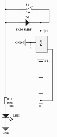
The last LED in the stack is NOT controlled, but merely acts as a power-applied indicator.
P.P.S.
I may end up dropping the allowable minimum to 9.5 so the values work out evenly as 5% resistors
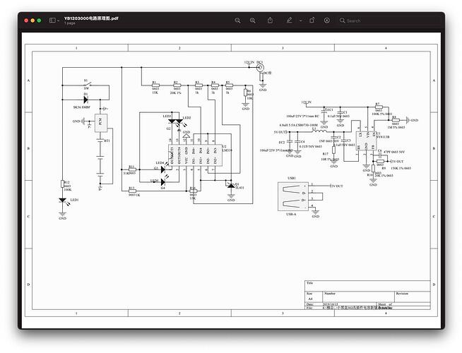
And yes, the State-of-Charge monitor is wired exactly upside-down, (that is, backwards with respect to inputs and reference voltage inputs). To correct it would require cutting and jumpering something like 12 traces or a complete PCB redesign for that circuit.
I’m going to try to figure out a way to do a simple single, (or two), cuts and jumpers repair. Not sure if it’s even possible.

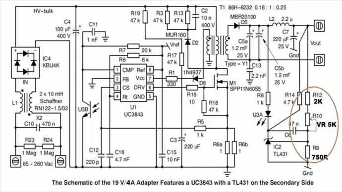
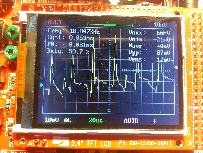

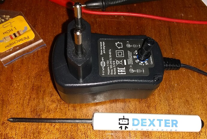
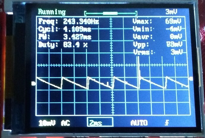


 – but even that would be a LOT of resistors.