Oh yes, the “pay it now or really pay later” discussion. You know I used to have a “soap box” on software quality, trying to convince software folks to “plan for what could go wrong”. No one liked my message, and I now believe that I was wrong to think my good ideas were good business. Business rewards the biggest risk takers, the fastest producers, and the willing to ignore reality folk. Eventually, I decided to stop trying to tell the business what was good for them, and let them know it was on them to figure out how to use me to their best advantage. Then I got tired and switched to QA where no one listens to you but you get to do your own thing.
Let me know if you get a new badge for a post with 100 replies out of this - that ought to be worth something?
I used to say: “Pay me now or pay me later - either way I’m gonna get paid.”
I also said: “I’ll take all the overtime you want to hand out.” with the implication that their idiocy was lining my pockets.
And it did!
Bought a house with all the money I banked.
In my case working in the aerospace industry had its advantages - folks like Boeing, McDonnell Douglas, Grumman, Northrop, (before they merged), the Department of Defense, and trivial folks like the FAA, get really pissed when your hardware/software screws up at 40,000 feet and the fines can be, (shall we say), just a bit painful.
I have always been a quality evangelist. My dad used to say “Only a complete ass does a half-assed job.”
Can you get more than one?
I got that badge back on the “Seeed Studios pH meter” thread.
If you are talking about the same machine I’m thinking about, I used one on my company’s AFIS, (airborne flight inspection system), project for the FAA.
The thing I remember was kinda’ a cross between a computer, a calculator on steroids, and a piece of test equipment. About the size of an Osbourne I and cranky as all hell.
Programmed in HP Basic, (IMHO the version I saw is what Python should have become.), and it could do anything - including wash the dishes - with the correct hardware interface plugged in. The fact that you could make your own interface cards was totally wizard!
Loved it, but they refused to let me touch the software so I did all my diagnostic software in Motorola 68000 assembler and uploaded Motorola HEX files directly to the main processor boards.
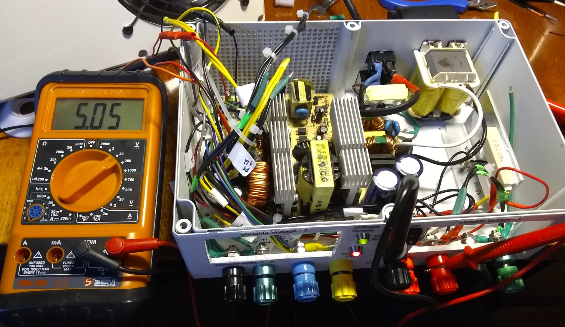
Today I discovered that the circuit ground from the power modules is not electrically the same as the common power ground from the power supply. Ergo, I can’t use the common circuit ground as the power module’s common return.
They are electrically connected, but not electrically identical, which is important as essential parts of the output filtering and sensing circuits may go through the ground circuit.
Likewise, I cannot use the power module’s ground as the common circuit ground because it might overload the sensitive circuitry inside the module and create an unbalanced return current the modules cannot compensate for.
Result:
I have to rearrange my common ground circuit to isolate the power module’s grounds and create a separate ground connection for all the fixed voltages.
(I’m not near my computer so I can’t make a schematic.)
The simplest example is two ground points separated by an inductor or a very low value of resistance.
They are connected, they may even measure as a short circuit, but electrically they are not identical.
In this case I suspect they are using a particular kind of filter for the output where both the voltage lead and the return lead circuits are wound around a toroidal core with the wires laying side by side. This is called a “bifilar” winding and it has interesting electrical properties that make it excellent for filtering.
Because of the relatively large size of the wires, it reads as a dead-short on my multimeter.
You are correct in the sense that most circuits carry the common ground through to the output, though in voltage conversion circuits this kind of circuit is not uncommon.
I should have checked first. Unfortunately I assumed that another circuit I saw was wired correctly. (Spoiler: It wasn’t.)
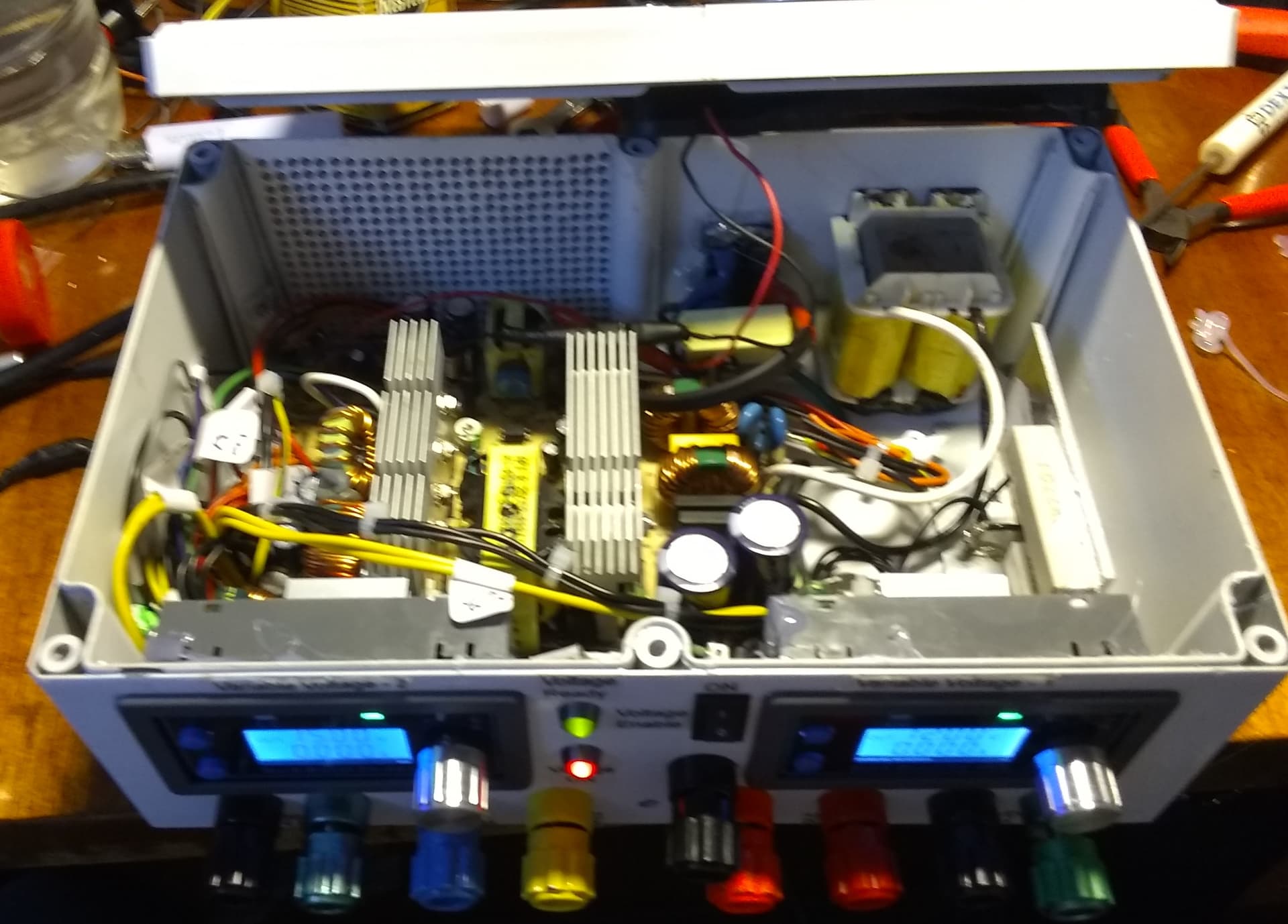
Now I have to do a major ground circuit redesign. Hopefully I won’t have to replace the box itself because I have to add yet another ground binding post for all the fixed voltages.
P.S.
It’s not ignorance per se, it’s just a totally different skill set. Both you and @cyclicalobsessive do things with code “that would cross a rabbi’s eyes!” (Fiddler on the Roof) I don’t expect you to be hardware engineers.
In addition to @jimrh’s explanation, I’ll risk talking without knowing what I’m talking about.
I think one example of “connected but not identical ground” is in our homes’ three wire outlets. Sometimes the white wire is the same as the safety ground wire, but if the outlet is GFI protected then the white wire first goes through the protection circuitry on its way to the same earth ground somewhere as the safety ground wire. Using a high impedance resistance meter will show both wires to be connected, but will not reveal that they are electrically not identical.
If the white wire and the safety ground wire were to be bridged at the outlet, (e.g. by a crazy homeowner doing his own electrical repairs), the GFI circuit would be messed up.
Another more extreme example might result from a trick I saw some RF guys use. I always assumed that the shield of a coax cable was connected to the outer connector part, but sometimes the RF guys would only connect one end of the shield to a connector to prevent “ground loops” raising the ground potential at distant points.
Them double-Es are double sneaky with their double-grounds sometimes.
Because, especially in small signal applications, ground loops can be a significant source of circuit noise. So much so that the noise can be orders of magnitude larger than the signal.
Not just RF, but low signal audio applications can be especially sensitive to ground loops.
I wasn’t clear - I was thinking joined by something with very low resistance (e.g. a wire). Didn’t realize they could still be different. Learn something new every day. Thanks @jimrh and @cyclicalobsessive for the examples.
/K
One of the reasons it is especially important in power conversion circuits, (and the final stages of an audio amplifier are simply a special kind of power conversion circuit), is that the circuit often handles significant current with respect to the output signal.
A large positive current pulse has a correspondingly large negative current pulse.
In the case of a DC supply, the “signal” is the absence of a signal.
Additionally, circuits often are extremely sensitive to voltage supply noise. Though a circuit may have trivial gain, (or in the case of a digital circuit, unity gain), the gain between the power rails and the output can be tens of thousands. Miniscule ripple can turn into a significant part of the output.
There are entire college classes on managing power supply noise and it’s not a simple topic.
I checked the vents in the back, and there’s lots of air flow, so I don’t think overheating will be a problem.
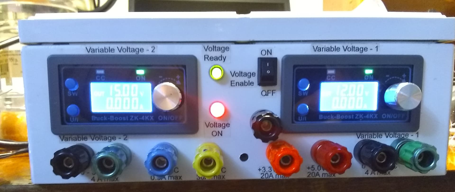
The next steps are to calibrate the two front panel voltage meters by adjusting to a known precision voltage output, and then adjusting the reading to match.
That, cover screws, and feet are all that remains.
I’m going to away for the next couple of weeks, but when I get back, (and clean up the mess!), I will continue the battery tests.
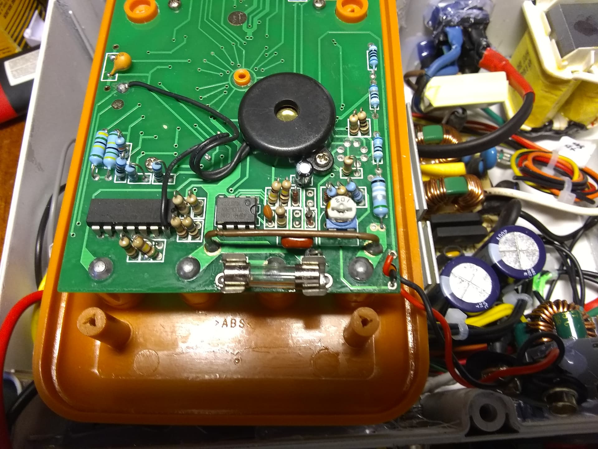
A piece of #14 solid copper wire is the 10 amp shunt resistor on my multimeter.
It’s the solid wire in the lower right hand corner. If you look really closely at the left side of the wire, you can see where they notched it with wire cutters to calibrate the resistance of the wire.
It will read as a dead-short on anything but a milli-ohmmeter.