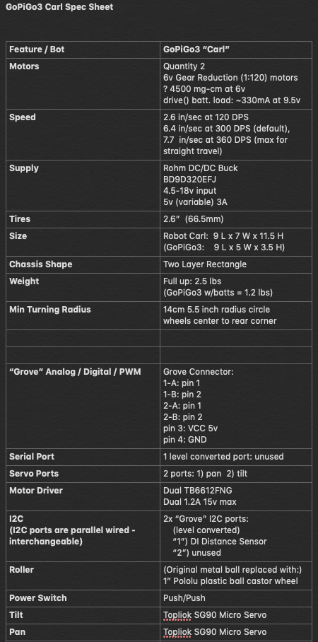
I would like to find - if possible - technical information about the red GoPiGo interface board.
Anything would be helpful, the more detailed the better. Detailed drawings, schematics, pin-outs, etc., would all be helpful.
This way I can make the GoPiGo do what I want it to do instead of what someone else wants it to do.
Possible?
Jim “JR”
=====================
Update:
I found this page: Hardware and Port Description
. . . that describes in somewhat superficial detail what the ports and LED’s do. However, significant information is still missing.
What are the A/D and I2c port pinouts? Supposedly they fit “Grove” accessories, but that doesn’t tell me anything. What if I have my own devices I want to use?
What is the serial port pinout?
Is there anything special programmatically I have to do to use these ports - especially the serial port - if I want to use something other than the default sensors/actuators?
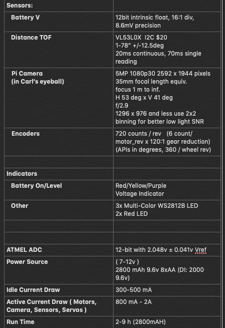
Fantastic! That explains the 9.something voltages I get during hardware test. Damn it all, I thought it was current-draw voltage droop and was tossing batteries!
Pity it’s closed, I’d up-vote that explanation by at least fifty. Matt’s obviously The Real Deal instead of some wannabe punter.
Jim “JR”
p.s. No, you’re not being pedantic. You are being curious and want to know what happens between point “A” and point “B” instead of taking it on blind faith. I salute you! Being nosy and picky about things like that is often the difference between a rocket getting into orbit or blowing up 16 seconds into lift-off.