Ugh, my odometry is terrible

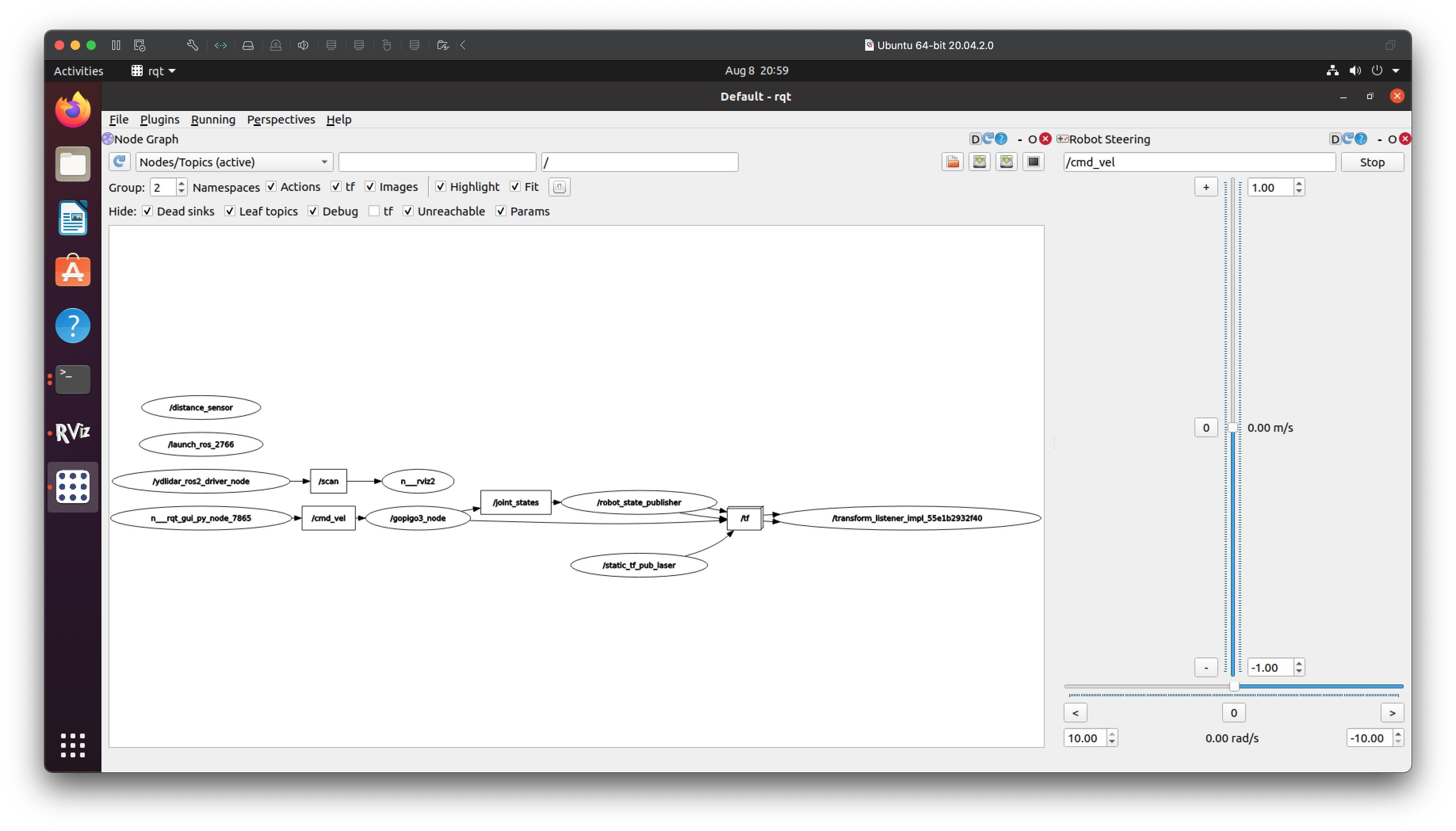
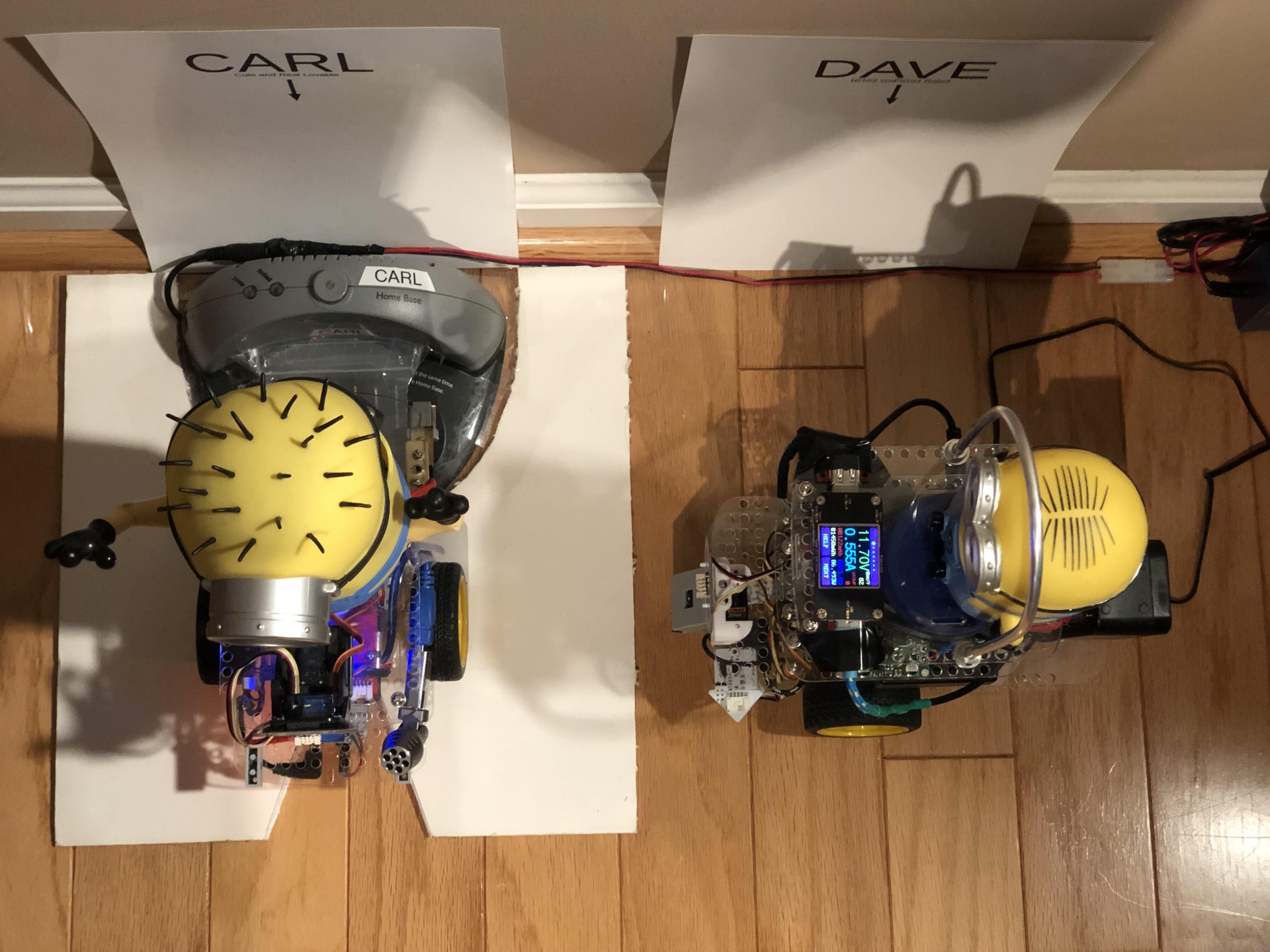
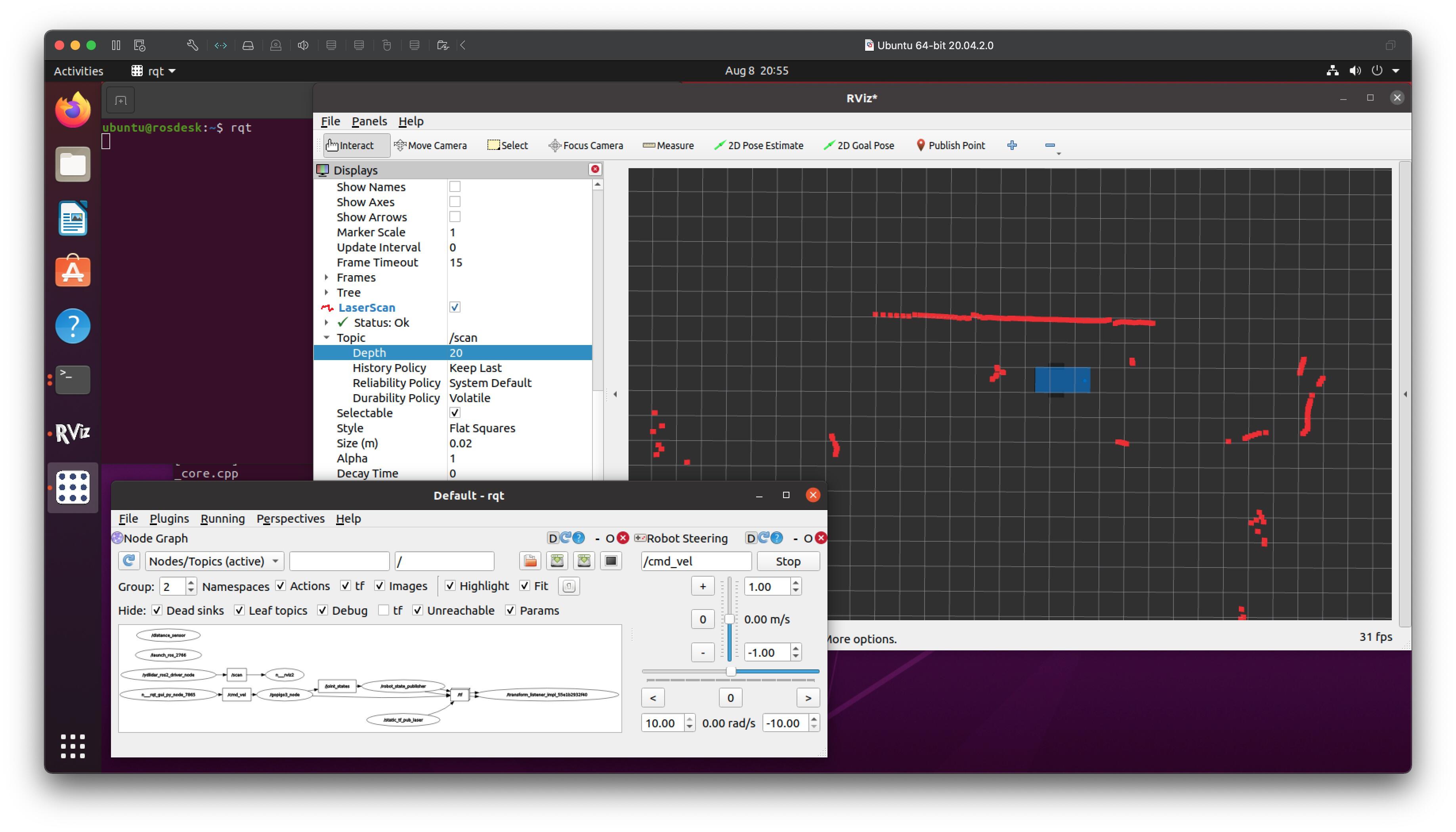
I was working on autonomous navigation in my “roboland” and not having much luck. The global planner would generate a path, but the robot wouldn’t follow it most of the time. Part of the problem seemed to be localization - when sitting still the robot jumped around a lot in RVIZ. But tweaking settings for the global and local planners didn’t seem to help.

I found this useful tutorial on the ROS site:
http://wiki.ros.org/navigation/Tutorials/Navigation%20Tuning%20Guide

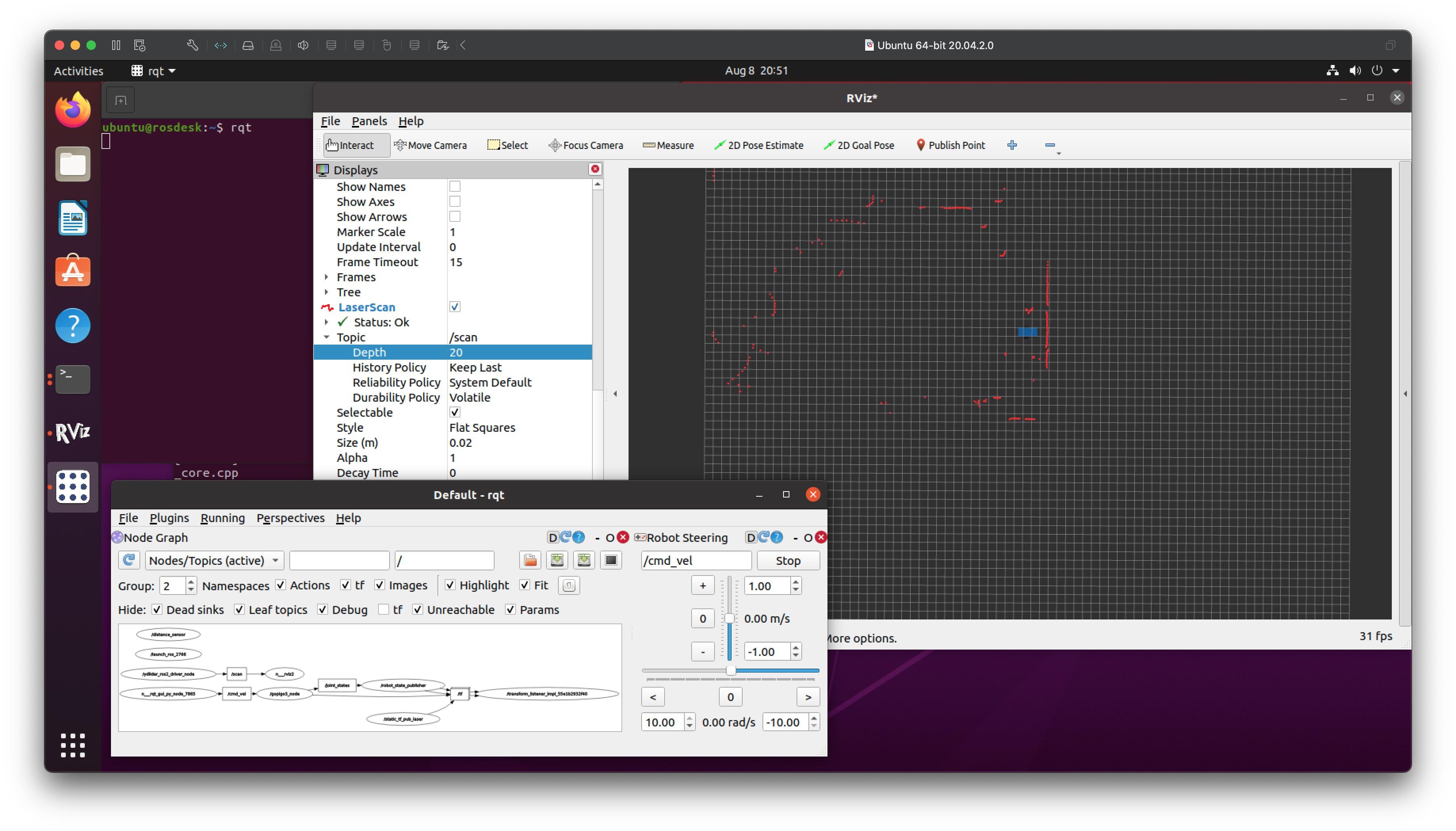
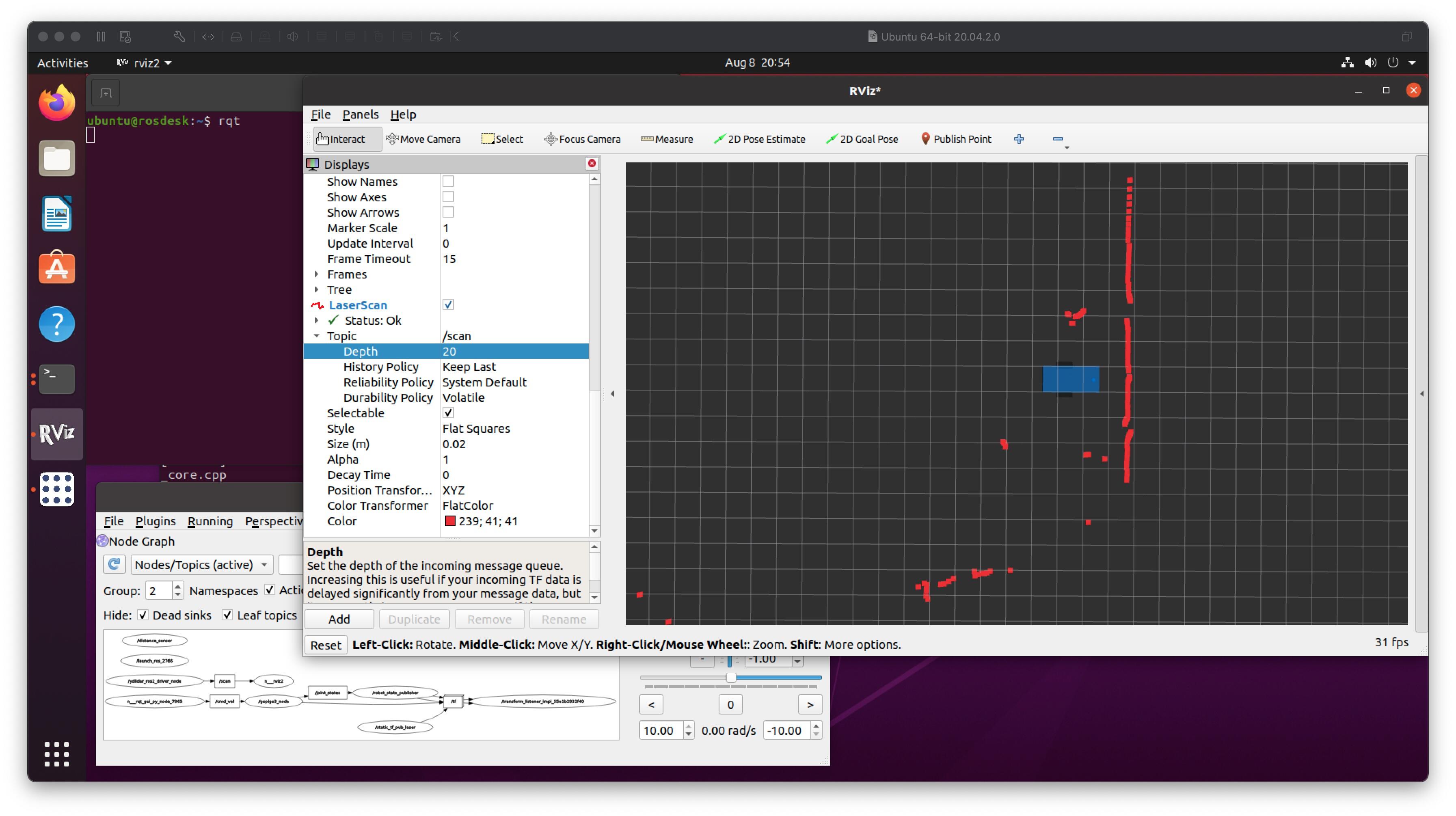
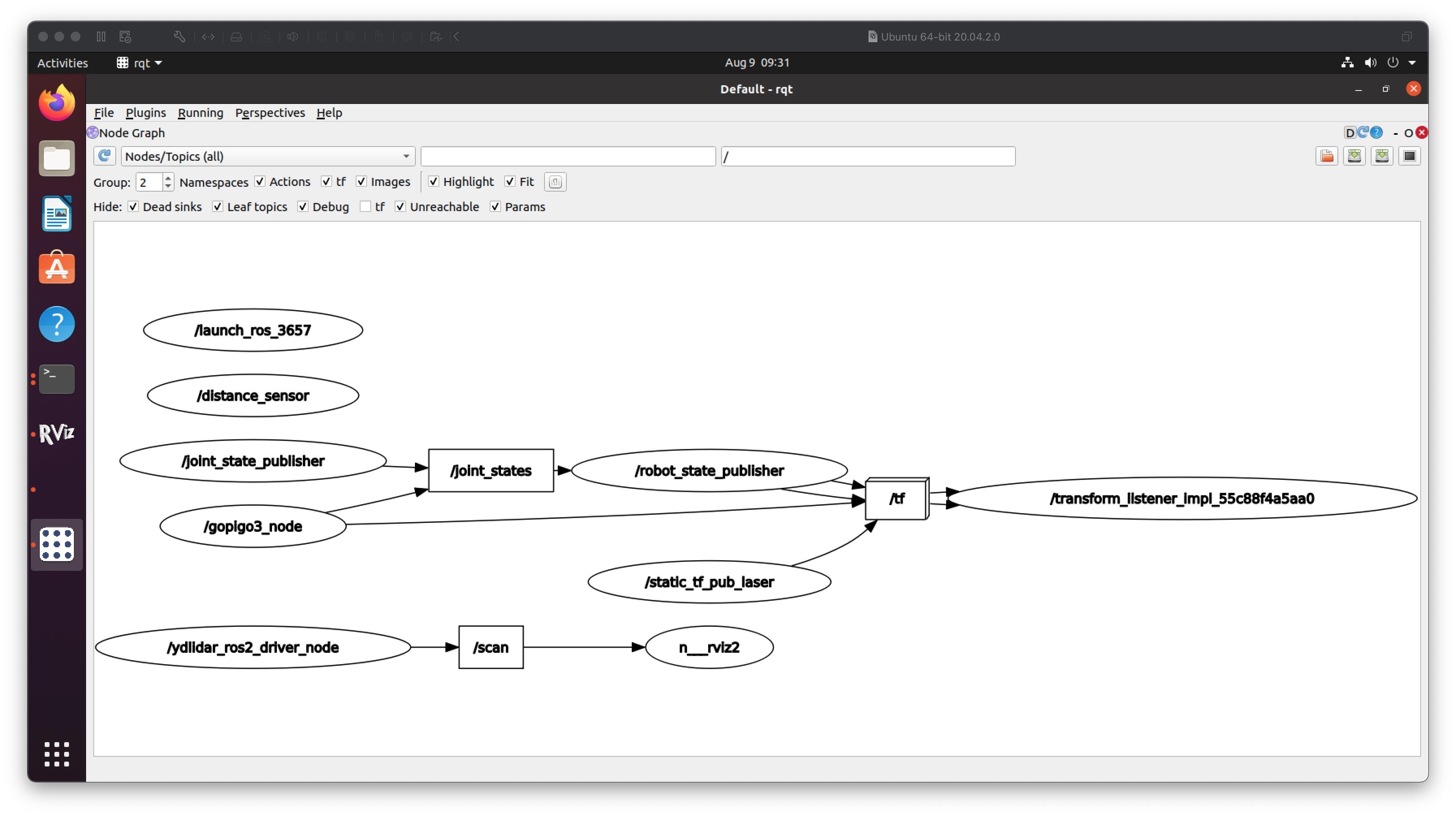
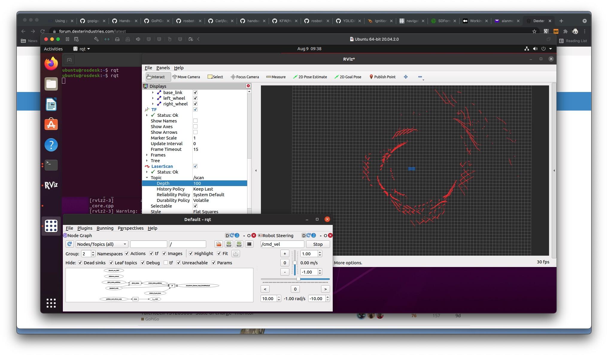
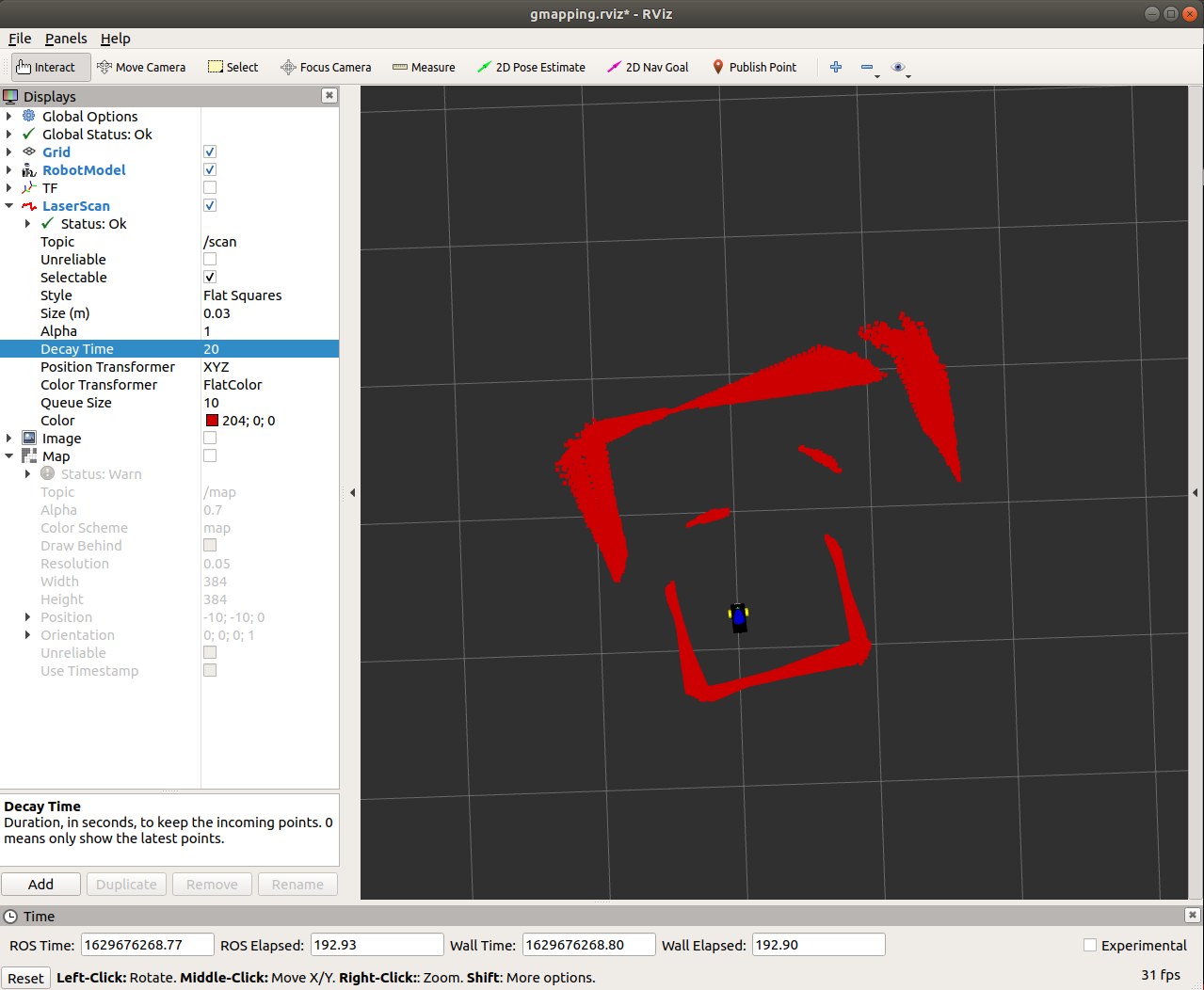
I only got to step 1.2 before I found trouble. I did the “turning in place test” suggested, only to discover my odometry seems to be terrible:

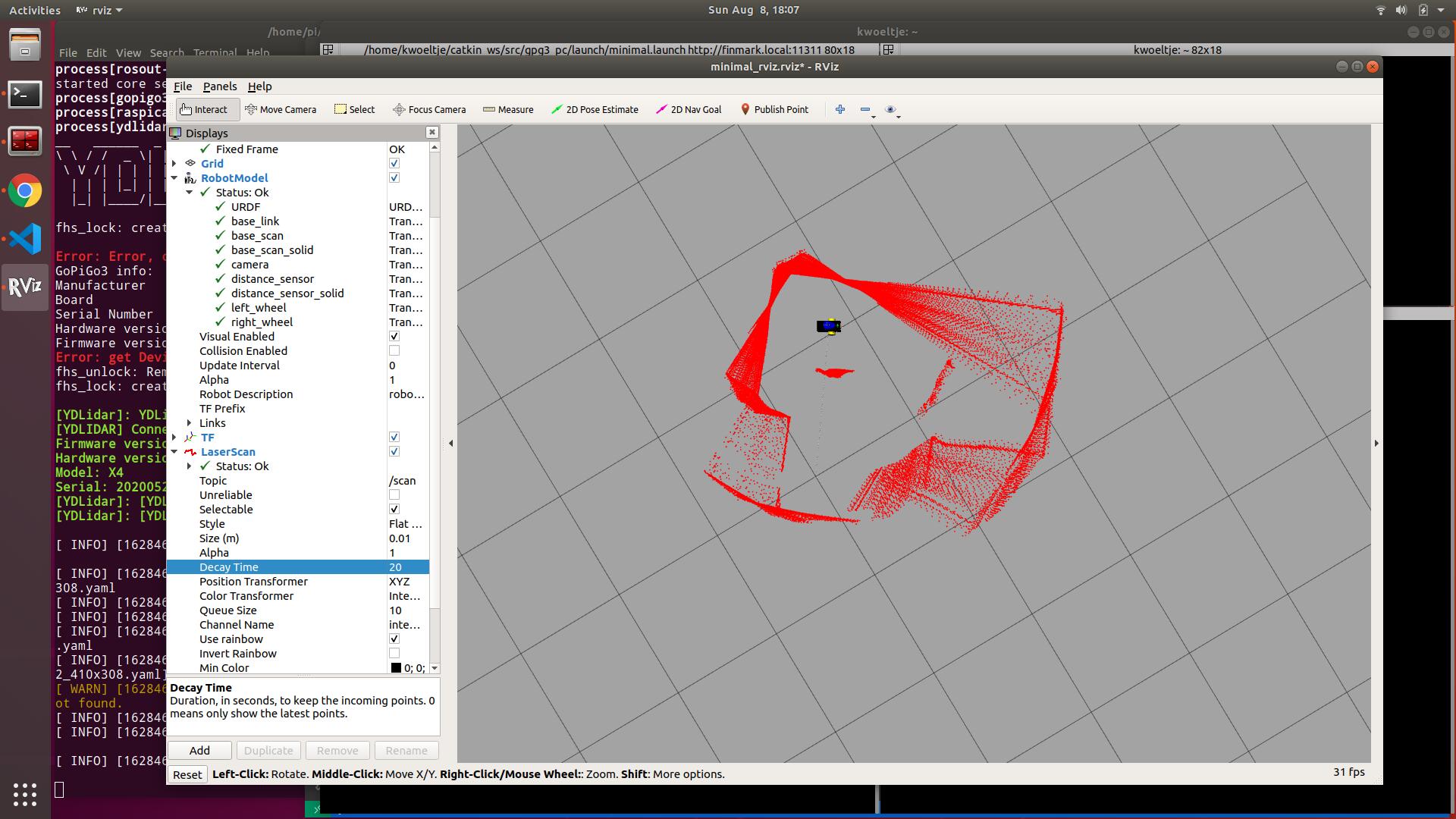
This is 20s of laser scan data superimposed (decay time of 20) with the fixed frame set to /Odom. The walls should stay in place but you’ll see the wide spread of the wall positions. So clearly I have a problem. This doesn’t explain my localization problem (the robot position being jittery even in place), but still a problem I’ll need to work on.

Right now I think /Odom is based entirely on the wheel encoders. I’ve got the wheel settings calibrated now, so that shouldn’t be an issue. One thing I’d like to do is figure out how to add in the IMU data.

@cyclicalobsessive - if you try this test what do you get? I’m wondering if it’s just me.

/K

2 Likes

I get everything matching expectations.

(I have joint state and robot state pub running - you said something about not having joint pub running?)

Here is starting up with Dave at “home” looking normal to wall:

and closeup:

Then turned roughly 90 right to be parallel to wall:

2 Likes

I have gopigo3 node publishing /odom (and /tf) at 30hz
I think my LIDAR is set to rotate at 5 scans per second - (I have not confirmed the actual observed /scan topic rate - forgot how to see that.)
rviz2 is updating the display at 30hz,
The scan depth was set to 20.

ydlidar_ros2_driver_node:
  ros__parameters:
    port: /dev/ttyUSB0
    frame_id: laser_frame
    ignore_array: ""
    baudrate: 128000
    lidar_type: 1
    device_type: 6
    sample_rate: 5
    abnormal_check_count: 4
    resolution_fixed: true
    reversion: false
    inverted: true  
    auto_reconnect: true
    isSingleChannel: false
    intensity: false
    support_motor_dtr: true
    angle_max: 180.0
    angle_min: -180.0
    range_max: 10.0
    range_min: 0.12
    frequency: 5.0
    invalid_range_is_inf: false

But Dave also turned very slowly so I could turn accurately 90 degrees. Maybe if Dave was turning very fast, there would be the same effect?

Maybe at 5 scans per second to get 20 seconds, I need to set depth to 100. I’ll try that tomorrow.

2 Likes

You need to make sure that the wheel_dia and wheel_base_width in the gopigo3.GoPiGo3() are set to your calibrated (if not using the latest which uses gpg3_config.json):

class GoPiGo3(object):
    WHEEL_BASE_WIDTH         = 117  # distance (mm) from left wheel to right wheel. This works with the initial GPG3 prototype. Will need to be adjusted.
    WHEEL_DIAMETER           = 66.5 # wheel diameter (mm)

Then the gopigo3 node will have your calibrations:

 WIDTH = gopigo3.GoPiGo3.WHEEL_BASE_WIDTH * 1e-3
    CIRCUMFERENCE = gopigo3.GoPiGo3.WHEEL_CIRCUMFERENCE * 1e-3

Note that the node is using the Class Definition values, not the Class Instance values - not a problem if you mod the Class to have your calibrations, but if using the new gopigo3.py which alters the instance values based on the calibration file, then the node is not getting the calibrated values.

AND I think those calibrations need to go into the urdf model:
left/right wheel radius for the wheel dia
left/right joint “y” values for the wheel base

My urdf does not have my correct WD and WB but when I rotate the robot 90 degrees, it does appear that the model rotates pretty much 90 degrees on the <fixed_frame>, so I don’t know how that is not affected.

2 Likes

To what extent should you have to normalize the data?

2 Likes

None. ROS is handling all coordinate transforms (if the right nodes are active)

2 Likes

Actually, I don’t see the joint state publisher in that rqt

And the reason - rqt is set to Active. When set to All it shows the joint pub present:

1 Like

Interesting - the scan displays properly for a long time, then briefly there is a second or two like yours, then the scan returns to only showing the single scan:

I don’t know if that “Frame Timeout: 15” with “Depth:100” which is 20 seconds means there are some old /tf still active. I really don’t understand any of this (yet).

I retried with depth 20, and set Dave spinning for a long time. There was a single, brief weird display, followed by all good displayed scans. It may be that there are some “Virtual Machine did not get cycles” happening, such that multiple scans pile up until the VM processes them all. I have “BOINC: Africa Rain Project” running 24/7 on my Mac at the moment, so perhaps the VM with OpenGL turned off is a little slow at processing frames to display… Too many variables; Too many configuration settings.

I think the joint_state_publisher_gui publishes a single joint state when it starts up, then is no longer active:

[joint_state_publisher_gui-2] [INFO] [1628517197.394491367] [joint_state_publisher]: Centering
2 Likes

I just set the “Decay Time” to 20 in the RVIZ GUI - that’s highlighted blue in my screen shot. This just keeps the markers for the laser scan on the screen for 20 sec - doesn’t mess with any of the other scan properties. Playing with it today 10 sec is plenty to see the problem.

Even when I turn slowly I get a wide spread of where it thinks the laser is.

that’s the part I have next on my list to check

Not sure what those do myself. And I don’t think it’s a joint state publisher problem - my tf’s seem to move appropriately. Since the fixed frame is /odom I think that’s the issue (as suggested by the trouble shooting tutorial). Now I just have to figure out how to fix that.

/K

2 Likes

Update: - Guessed wrong - Ignore.

Question: does the color transformer have “flat color”? That is what mine is set to. I see yours says something like “integrative”? (wrong - probably “Intensity”).

1 Like

It is intensity. But what you can’t see on the screenshot is that a little further down there are settings for Min Intensity and Max Intensity. Both are set to 2 (and there’s a checkbox that says autocompute color bounds) so it ends up being a flat color.

/K

1 Like

I was thinking about this trying to come up with some idea what could be going on. A couple things came to mind:

  • Have you dusted the playground and dusted Finmark’s wheels lately?
  • Perhaps try my wheelBaseRotateTest.py. With your calibrations, can you x10 360deg turns and have it end up pretty close to the original?
  • I don’t know how with the LIDAR on top, you could temporarily mount the battery closer to the two wheels, but I found Carl’s turning accuracy to improve immensely with the battery on the top plate. That is exactly why Dave has the extra layer for the LIDAR so that I could mount the battery more forward taking weight off the castor.
1 Like

Thanks for the ideas.

The wheels and the playground aren’t dusty, and I think I’m stuck with the geometry. But I’ll try the rotate test and see where it gets me. I’m traveling, so I’ll do it when I’m back home.

/K

2 Likes

Hi @KeithW, (Heavily edited post so ignore any emailed versions)

Moving back a link from the Tuning Guide, to:
navigation/Tutorials/RobotSetup/TF - ROS Wiki
I read:

“base_link” (for navigation, its important that this be placed at the rotational center of the robot)

and wondered what we are using?

The base_link of the URDF models of “Hands On ROS For Robotic Programming” is the center of a square box, and the wheels rotate about that base_link:

 <joint name="joint_left_wheel" type="continuous">
    <parent link="base_link"/>
    <child link="left_wheel"/>
    <origin xyz="0 0.30 0" rpy="0 0 0" /> 
    <axis xyz="0 1 0" />
  </joint>

I thought I followed the book’s pattern in building Dave’s URDF model, keeping the base_link at the center of the body box, and offset the wheels 20mm forward of the center of the box:

<joint name="joint_left_wheel" type="continuous">
    <parent link="base_link"/>
    <child link="left_wheel"/>
    <origin xyz="0.020 0.058 0.0325" rpy="0 0 0" /> 
    <axis xyz="0 1 0" />
  </joint>

Do you have your center of rotation at the base_link?

Somewhere I copied something I called keith_gpg.urdf which would seem to have your center of rotation 100mm in front of the base_link:

<!-- Left Wheel JOINT base_link -->
  <joint name="joint_left_wheel" type="continuous">
    <parent link="base_link"/>
    <child link="left_wheel"/>
    <origin xyz="0.1 0.15 0.0125" rpy="0 0 0" /> 
    <axis xyz="0 1 0"/>
  </joint>

Apparently it is important that the wheel link x value be 0, so I need to change my base_link visual box, the castor, the distance sensor joint, and the joint_ydlidar to put everything relative to the virtual axle between the wheels.

What I’m rebuilding my URDF with:

<!-- GoPiGo3 as 216mm long,  103mm wide, 4mm thick plates (blue) -->
<!--   with a 3/4 inch castor holding the chassis level (blue) -->
<!--   with (effective) 66.77mm dia 25mm wide wheels (black) spaced 106mm (Wheel base) apart -->
<!--   NOTE: The center of rotation must be at xyz="0 0 X" of the base link -->
<!--         therefore the wheel joints' x value must be 0 -->
<!--   The chassis center is 20mm back of the center of rotation (wheels) -->
<!--   DI Distance Sensor is 95mm in front of wheels -->
<!--   The LIDAR is ~22mm behind the center of rotation (wheels) -->
<!--       (A bit hard to measure after assembled.)

1 Like

Good catch - I’ll have to look. I’ve been meaning to update my URDF, so this provides a good reason.
/K

2 Likes

It is a real PITB! I’ve got the visual for Dave updated for the most part, only have the distance sensor to figure out why it is sticking way out. My dave.urdf is here.

2 Likes

No pressure or anything, but I’m checking twice a day to hear how you’re gettin’ on with this issue.

Finmark might have been telling you he’s in love with this bot:
FinmarkArt
She’s quite a looker, that one.

2 Likes

It’s a good thing that there isn’t an enemy submarine at the end of that scan. :wink:

I have every confidence that the two of you will get that figured out.
:+1:

2 Likes

Thanks - I was just looking at my URDF yesterday and was thinking about making it more realistic. But not sure that that matters for navigation which I think uses the URDF for the tf’s and to estimate clearance. I think it matters more for simulation to get all of the masses in the right spot.

/K

2 Likes

OK - calibration and getting the URDF a bit more correct seems to have helped.

Unlike @cyclicalobsessive, I decided to keep my URDF stylized. However I did try to get the size of the overall robot better, as well are getting wheel size and placement more correct. Also got the base_link between the wheels (at least in the xy-plane).

Here’s what it looks like in RVIZ


Note that I got rid of the distance sensor solid since it didn’t really look like the distance sensor on the GoPiGo3. I just modeled a white slab (not wanting to fool with the actual stadium shape of the real distance sensor).

The body is translucent for Gazebo.


I included a blue slab for the IMU, although I don’t actually have that implemented yet.

When I did the 360-spin in place test, note that the results aren’t nearly as bad as they were.


As I’m writing this up I may try moving the base_link to literally between the wheels (z-axis as well) to see if that helps.

/K

2 Likes