Karan,
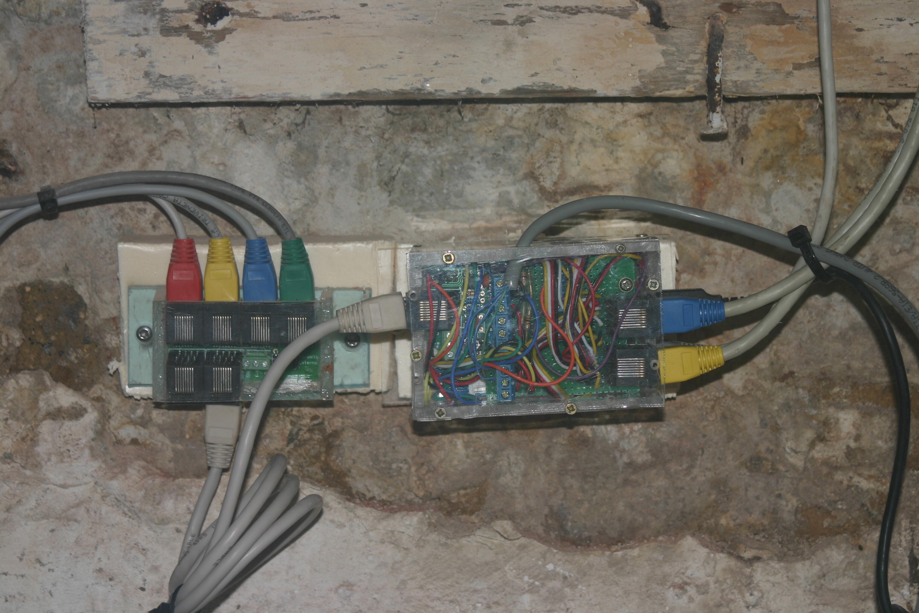
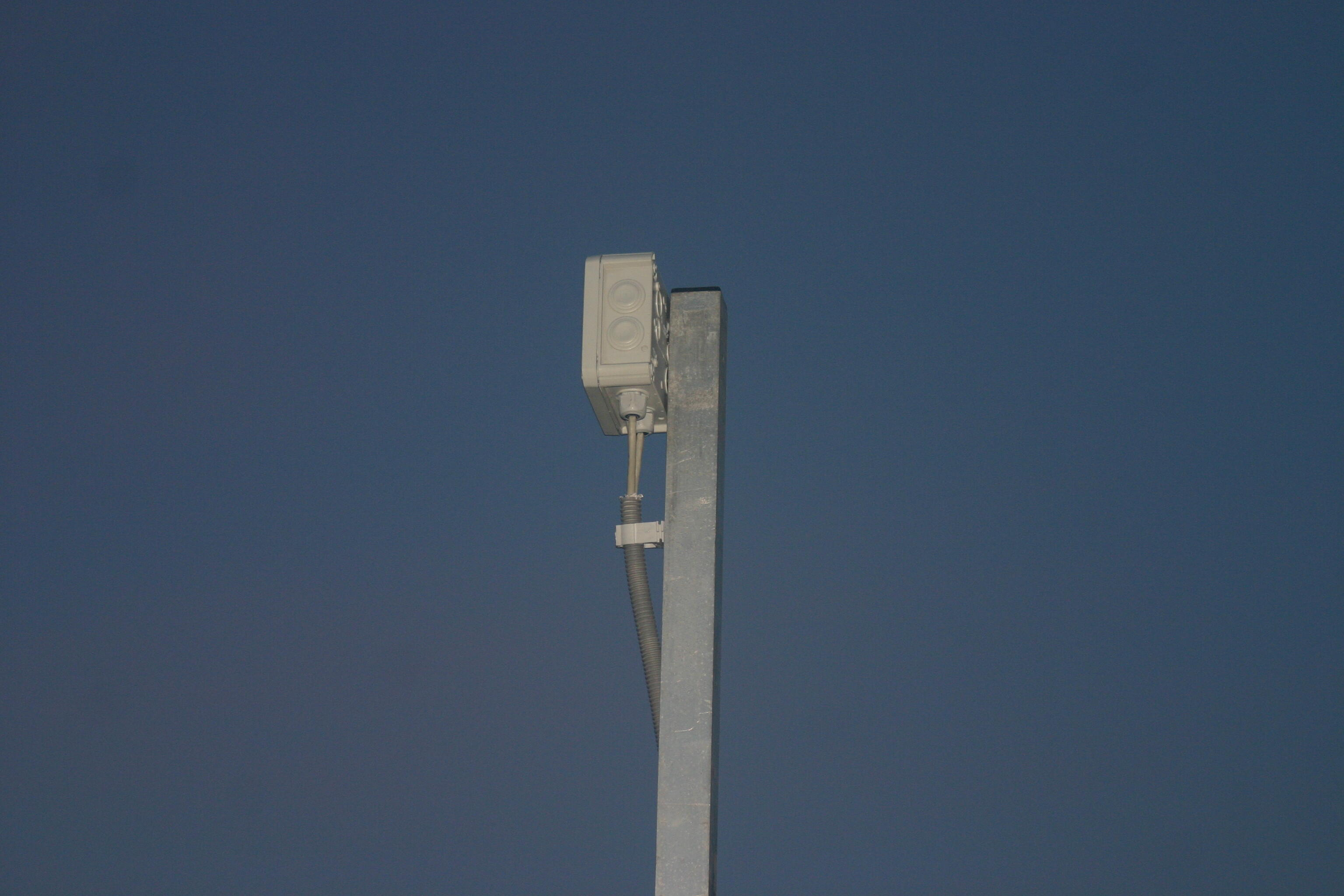
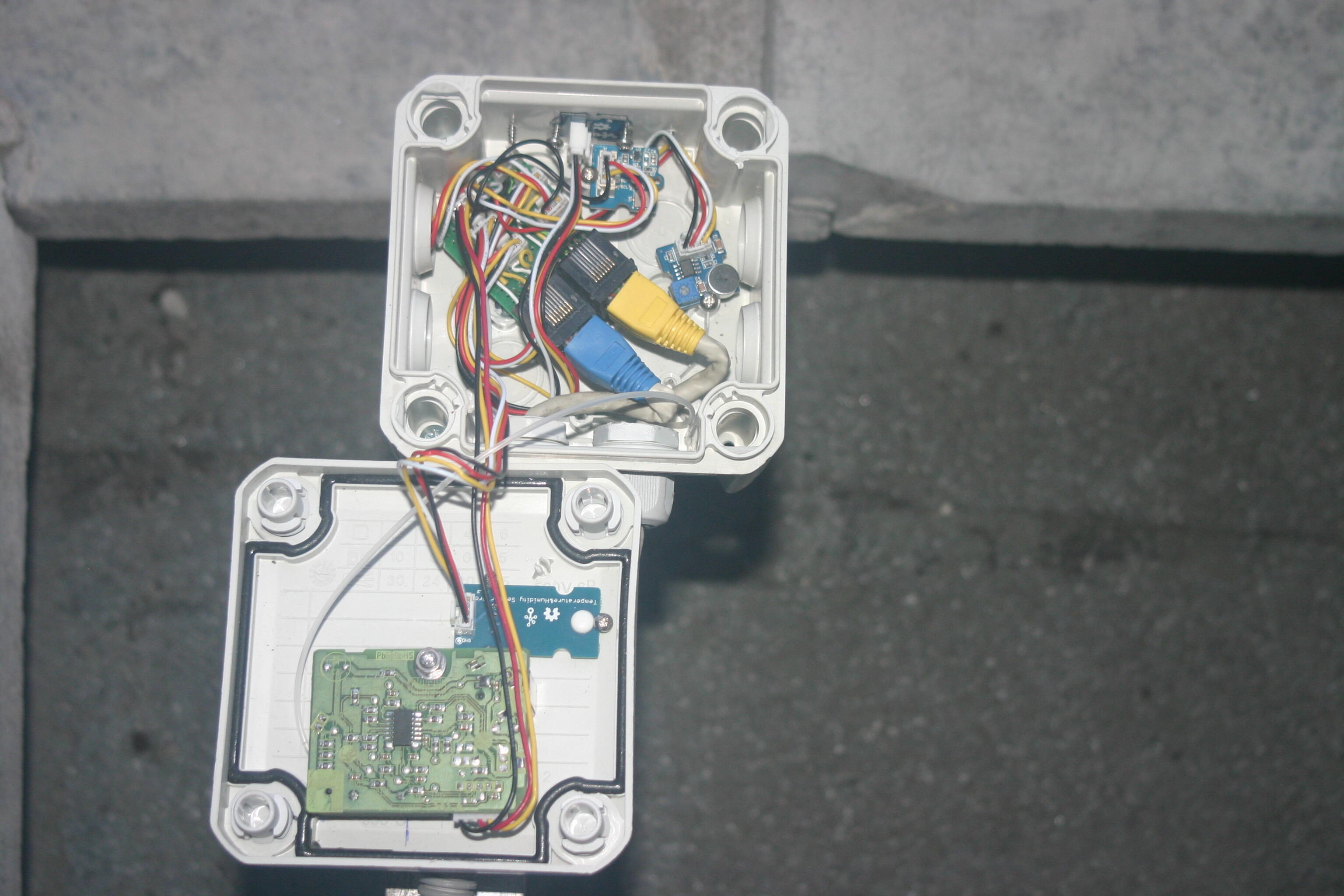
Since I wasn’t sure the sensors were broken because all the sensors are mounted in a sensorbox on a pool on my roof and 2 UTP cat6 cables ensure the connection with the GrovePi (wich is on the RaspberryPi) in my cellar. One of these UTP-cables is used for the Grove analog Sound Sensor, the Grove Temp. & Humidity Sensor Pro and the Grove Dust Sensor and these seem to work (but neither of these sensors is I2C, there analog or digital). The other UTP-cable is used for connecting all the I2C-sensors (e.g. the Grove Barometic Sensor and the Grove Digital Light Sensor) and neither of them is detected by sudo i2cdetect -y 1.
So it could be broken sensors or a wrong wiring on the second UTP-cable. To check the wrong wiring I need to get up the roof again and we had a full week of heavy rain, so that wasn’t on option. I therefore ordered a new Grove Barometic sensor and a new Grove Digital Light sensor from Seeds Technology. They arrived yesterday.
I then unplugged the Grove-wires in the GrovePi I2C-ports (making sure both I2C-sensors on the roof and the UTP-cable are’t connected anymore) and plugged in the new Grove Digital Light Sensor in the GrovePi I2C-1 port and the Grove Barometic Sensor in the GrovePi I2C-2 port. Then I ran the sudo i2cdetect -y 1 command and got this result:
pi@raspberrypi ~ $ sudo i2cdetect -y 1
     0  1  2  3  4  5  6  7  8  9  a  b  c  d  e  f
00:          -- 04 -- -- -- -- -- -- -- -- -- -- --
10: -- -- -- -- -- -- -- -- 18 -- -- -- -- -- -- --
20: -- -- -- -- -- -- -- -- -- 29 -- -- -- -- -- --
30: -- -- -- -- -- -- -- -- -- -- -- UU -- -- -- --
40: -- -- -- -- -- -- -- -- -- -- -- -- -- -- -- --
50: -- UU -- -- -- -- -- -- -- -- -- -- -- -- -- --
60: -- -- -- -- -- -- -- -- -- -- -- -- -- -- -- --
70: -- -- -- -- -- -- -- 77
pi@raspberrypi ~ $
All sensors are detected:
- 0x04 is the GrovePi.
- 0x18 is my RPI2 I2C 1-Wire host adaptor for Raspberry Pi from Sheepwalker Electronics (which I use to read my DS18B20 one-wire digital temperature sensors).
- 0x029 is the Grove Digital Light Sensor (whose sensor is a TSL2561, so it's NOT 0x039 as was mentioned in the libraries I found for the TSL2561).
- 0x077 is the Grove Barometic Sensor (whose sensor is the BMP085).
I then just had to addapt the Adafruit_I2C.py (change the bus to smbus.SMBus(1) in stead of smbus.SMBus(0) since my sensors are on I2C 1 bus) and correct the altitude by setting the barometic pressure at sea level in Belgium (you can find this on line at the KMI website, look at the value of “Middelkerke” which is situated at the shore. Today at 10 AM the pressure at sea level is 1019,0 hPa so in the Adafruit_BMP085_example.py the code should be altitude = bmp.readAltitude(101900) in stead of altitude = bmp.readAltitude().
And in the Adafruit_BMP085.py the code should be def readAltitude(self, seaLevelPressure=101900): in stead of def readAltitude(self, seaLevelPressure=101325):.
The full script of adapted Adafruit_BMP085_example.py is here:
#!/usr/bin/python

import smbus
import grovepi
from Adafruit_BMP085 import BMP085

# ===========================================================================
# Example Code
# ===========================================================================

# Initialise the BMP085 and use STANDARD mode (default value)
# bmp = BMP085(0x77, debug=True)
bmp = BMP085(0x77, 1)

# To specify a different operating mode, uncomment one of the following:
# bmp = BMP085(0x77, 0)  # ULTRALOWPOWER Mode
# bmp = BMP085(0x77, 1)  # STANDARD Mode
# bmp = BMP085(0x77, 2)  # HIRES Mode
# bmp = BMP085(0x77, 3)  # ULTRAHIRES Mode

bus = smbus.SMBus(1)

temp = bmp.readTemperature()

# Read the current barometric pressure level
pressure = bmp.readPressure()

# To calculate altitude based on an estimated mean sea level pressure
# (1013.25 hPa) call the function as follows, but this won't be very accurate
# altitude = bmp.readAltitude()

# To specify a more accurate altitude, enter the correct mean sea level
# pressure level.  For example, if the current pressure level is 1018.70 hPa
# enter 101870 since we include two decimal places in the integer value
altitude = bmp.readAltitude(101900)

print "Temperature: %.2f C" % temp
print "Pressure:    %.2f hPa" % (pressure / 100.0)
print "Altitude:    %.2f" % altitude
The full script of the adapted Adafruit_BMP085.py is here:
#!/usr/bin/python

import time
from Adafruit_I2C import Adafruit_I2C

# ===========================================================================
# BMP085 Class
# ===========================================================================

class BMP085 :
  i2c = None

  # Operating Modes
  __BMP085_ULTRALOWPOWER     = 0
  __BMP085_STANDARD          = 1
  __BMP085_HIGHRES           = 2
  __BMP085_ULTRAHIGHRES      = 3

  # BMP085 Registers
  __BMP085_CAL_AC1           = 0xAA  # R   Calibration data (16 bits)
  __BMP085_CAL_AC2           = 0xAC  # R   Calibration data (16 bits)
  __BMP085_CAL_AC3           = 0xAE  # R   Calibration data (16 bits)
  __BMP085_CAL_AC4           = 0xB0  # R   Calibration data (16 bits)
  __BMP085_CAL_AC5           = 0xB2  # R   Calibration data (16 bits)
  __BMP085_CAL_AC6           = 0xB4  # R   Calibration data (16 bits)
  __BMP085_CAL_B1            = 0xB6  # R   Calibration data (16 bits)
  __BMP085_CAL_B2            = 0xB8  # R   Calibration data (16 bits)
  __BMP085_CAL_MB            = 0xBA  # R   Calibration data (16 bits)
  __BMP085_CAL_MC            = 0xBC  # R   Calibration data (16 bits)
  __BMP085_CAL_MD            = 0xBE  # R   Calibration data (16 bits)
  __BMP085_CONTROL           = 0xF4
  __BMP085_TEMPDATA          = 0xF6
  __BMP085_PRESSUREDATA      = 0xF6
  __BMP085_READTEMPCMD       = 0x2E
  __BMP085_READPRESSURECMD   = 0x34

  # Private Fields
  _cal_AC1 = 0
  _cal_AC2 = 0
  _cal_AC3 = 0
  _cal_AC4 = 0
  _cal_AC5 = 0
  _cal_AC6 = 0
  _cal_B1 = 0
  _cal_B2 = 0
  _cal_MB = 0
  _cal_MC = 0
  _cal_MD = 0

  # Constructor
  def __init__(self, address=0x77, mode=1, debug=False):
    self.i2c = Adafruit_I2C(address)

    self.address = address
    self.debug = debug
    # Make sure the specified mode is in the appropriate range
    if ((mode < 0) | (mode > 3)):
      if (self.debug):
        print "Invalid Mode: Using STANDARD by default"
      self.mode = self.__BMP085_STANDARD
    else:
      self.mode = mode
    # Read the calibration data
    self.readCalibrationData()

  def readS16(self, register):
    "Reads a signed 16-bit value"
    hi = self.i2c.readS8(register)
    lo = self.i2c.readU8(register+1)
    return (hi << 8) + lo

  def readU16(self, register):
    "Reads an unsigned 16-bit value"
    hi = self.i2c.readU8(register)
    lo = self.i2c.readU8(register+1)
    return (hi << 8) + lo

  def readCalibrationData(self):
    "Reads the calibration data from the IC"
    self._cal_AC1 = self.readS16(self.__BMP085_CAL_AC1)   # INT16
    self._cal_AC2 = self.readS16(self.__BMP085_CAL_AC2)   # INT16
    self._cal_AC3 = self.readS16(self.__BMP085_CAL_AC3)   # INT16
    self._cal_AC4 = self.readU16(self.__BMP085_CAL_AC4)   # UINT16
    self._cal_AC5 = self.readU16(self.__BMP085_CAL_AC5)   # UINT16
    self._cal_AC6 = self.readU16(self.__BMP085_CAL_AC6)   # UINT16
    self._cal_B1 = self.readS16(self.__BMP085_CAL_B1)     # INT16
    self._cal_B2 = self.readS16(self.__BMP085_CAL_B2)     # INT16
    self._cal_MB = self.readS16(self.__BMP085_CAL_MB)     # INT16
    self._cal_MC = self.readS16(self.__BMP085_CAL_MC)     # INT16
    self._cal_MD = self.readS16(self.__BMP085_CAL_MD)     # INT16
    if (self.debug):
      self.showCalibrationData()

  def showCalibrationData(self):
      "Displays the calibration values for debugging purposes"
      print "DBG: AC1 = %6d" % (self._cal_AC1)
      print "DBG: AC2 = %6d" % (self._cal_AC2)
      print "DBG: AC3 = %6d" % (self._cal_AC3)
      print "DBG: AC4 = %6d" % (self._cal_AC4)
      print "DBG: AC5 = %6d" % (self._cal_AC5)
      print "DBG: AC6 = %6d" % (self._cal_AC6)
      print "DBG: B1  = %6d" % (self._cal_B1)
      print "DBG: B2  = %6d" % (self._cal_B2)
      print "DBG: MB  = %6d" % (self._cal_MB)
      print "DBG: MC  = %6d" % (self._cal_MC)
      print "DBG: MD  = %6d" % (self._cal_MD)

  def readRawTemp(self):
    "Reads the raw (uncompensated) temperature from the sensor"
    self.i2c.write8(self.__BMP085_CONTROL, self.__BMP085_READTEMPCMD)
    time.sleep(0.005)  # Wait 5ms
    raw = self.readU16(self.__BMP085_TEMPDATA)
    if (self.debug):
      print "DBG: Raw Temp: 0x%04X (%d)" % (raw & 0xFFFF, raw)
    return raw

  def readRawPressure(self):
    "Reads the raw (uncompensated) pressure level from the sensor"
    self.i2c.write8(self.__BMP085_CONTROL, self.__BMP085_READPRESSURECMD + (self.mode << 6))
    if (self.mode == self.__BMP085_ULTRALOWPOWER):
      time.sleep(0.005)
    elif (self.mode == self.__BMP085_HIGHRES):
      time.sleep(0.014)
    elif (self.mode == self.__BMP085_ULTRAHIGHRES):
      time.sleep(0.026)
    else:
      time.sleep(0.008)
    msb = self.i2c.readU8(self.__BMP085_PRESSUREDATA)
    lsb = self.i2c.readU8(self.__BMP085_PRESSUREDATA+1)
    xlsb = self.i2c.readU8(self.__BMP085_PRESSUREDATA+2)
    raw = ((msb << 16) + (lsb << 8) + xlsb) >> (8 - self.mode)
    if (self.debug):
      print "DBG: Raw Pressure: 0x%04X (%d)" % (raw & 0xFFFF, raw)
    return raw

  def readTemperature(self):
    "Gets the compensated temperature in degrees celcius"
    UT = 0
    X1 = 0
    X2 = 0
    B5 = 0
    temp = 0.0

    # Read raw temp before aligning it with the calibration values
    UT = self.readRawTemp()
    X1 = ((UT - self._cal_AC6) * self._cal_AC5) >> 15
    X2 = (self._cal_MC << 11) / (X1 + self._cal_MD)
    B5 = X1 + X2
    temp = ((B5 + 8) >> 4) / 10.0
    if (self.debug):
      print "DBG: Calibrated temperature = %f C" % temp
    return temp

  def readPressure(self):
    "Gets the compensated pressure in pascal"
    UT = 0
    UP = 0
    B3 = 0
    B5 = 0
    B6 = 0
    X1 = 0
    X2 = 0
    X3 = 0
    p = 0
    B4 = 0
    B7 = 0

    UT = self.readRawTemp()
    UP = self.readRawPressure()

    # You can use the datasheet values to test the conversion results
    # dsValues = True
    dsValues = False

    if (dsValues):
      UT = 27898
      UP = 23843
      self._cal_AC6 = 23153
      self._cal_AC5 = 32757
      self._cal_MB = -32768;
      self._cal_MC = -8711
      self._cal_MD = 2868
      self._cal_B1 = 6190
      self._cal_B2 = 4
      self._cal_AC3 = -14383
      self._cal_AC2 = -72
      self._cal_AC1 = 408
      self._cal_AC4 = 32741
      self.mode = self.__BMP085_ULTRALOWPOWER
      if (self.debug):
        self.showCalibrationData()

    # True Temperature Calculations
    X1 = ((UT - self._cal_AC6) * self._cal_AC5) >> 15
    X2 = (self._cal_MC << 11) / (X1 + self._cal_MD)
    B5 = X1 + X2
    if (self.debug):
      print "DBG: X1 = %d" % (X1)
      print "DBG: X2 = %d" % (X2)
      print "DBG: B5 = %d" % (B5)
      print "DBG: True Temperature = %.2f C" % (((B5 + 8) >> 4) / 10.0)

    # Pressure Calculations
    B6 = B5 - 4000
    X1 = (self._cal_B2 * (B6 * B6) >> 12) >> 11
    X2 = (self._cal_AC2 * B6) >> 11
    X3 = X1 + X2
    B3 = (((self._cal_AC1 * 4 + X3) << self.mode) + 2) / 4
    if (self.debug):
      print "DBG: B6 = %d" % (B6)
      print "DBG: X1 = %d" % (X1)
      print "DBG: X2 = %d" % (X2)
      print "DBG: X3 = %d" % (X3)
      print "DBG: B3 = %d" % (B3)

    X1 = (self._cal_AC3 * B6) >> 13
    X2 = (self._cal_B1 * ((B6 * B6) >> 12)) >> 16
    X3 = ((X1 + X2) + 2) >> 2
    B4 = (self._cal_AC4 * (X3 + 32768)) >> 15
    B7 = (UP - B3) * (50000 >> self.mode)
    if (self.debug):
      print "DBG: X1 = %d" % (X1)
      print "DBG: X2 = %d" % (X2)
      print "DBG: X3 = %d" % (X3)
      print "DBG: B4 = %d" % (B4)
      print "DBG: B7 = %d" % (B7)

    if (B7 < 0x80000000):
      p = (B7 * 2) / B4
    else:
      p = (B7 / B4) * 2

    if (self.debug):
      print "DBG: X1 = %d" % (X1)

    X1 = (p >> 8) * (p >> 8)
    X1 = (X1 * 3038) >> 16
    X2 = (-7357 * p) >> 16
    if (self.debug):
      print "DBG: p  = %d" % (p)
      print "DBG: X1 = %d" % (X1)
      print "DBG: X2 = %d" % (X2)

    p = p + ((X1 + X2 + 3791) >> 4)
    if (self.debug):
      print "DBG: Pressure = %d Pa" % (p)

    return p

  def readAltitude(self, seaLevelPressure=101900):
    "Calculates the altitude in meters"
    altitude = 0.0
    pressure = float(self.readPressure())
    altitude = 44330.0 * (1.0 - pow(pressure / seaLevelPressure, 0.1903))
    if (self.debug):
      print "DBG: Altitude = %d" % (altitude)
    return altitude

    return 0
This is the result:
pi@raspberrypi ~ $ sudo python Adafruit_BMP085_example.py
Error accessing 0x77: Check your I2C address
Temperature: 19.50 C
Pressure:    1011.83 hPa
Altitude:    3.56
pi@raspberrypi ~ $
For some reason I don’t understand, it first gives an error about the I2C address, but the rest of the script is performed correctly and the results are good. The sensor is actualy 0.57m below the street level and the altitude at street level is here 5.16m. The correct level is 4.59m and the measurement gives me 3.56m, wich is 1.03m lower. Since 1 hPa pressure means an altitude change of 8.5m (or 1m change in altitude give a pressure difference of 0,12 hPa), this difference is can be neglected.
But when I run the script again, it gives multiple times the same error:
pi@raspberrypi ~ $ sudo python Adafruit_BMP085_example.py
Error accessing 0x77: Check your I2C address
Error accessing 0x77: Check your I2C address
Error accessing 0x77: Check your I2C address
Temperature: 19.70 C
Pressure:    -231.96 hPa
Altitude:    -15.89
And when I ran it again it even stopt during an error:
pi@raspberrypi ~ $ sudo python Adafruit_BMP085_example.py
Error accessing 0x77: Check your I2C address
Error accessing 0x77: Check your I2C address
Error accessing 0x77: Check your I2C address
Error accessing 0x77: Check your I2C address
Error accessing 0x77: Check your I2C address
Error accessing 0x77: Check your I2C address
Traceback (most recent call last):
  File "Adafruit_BMP085_example.py", line 35, in <module>
    altitude = bmp.readAltitude(101870)
  File "/home/pi/Adafruit_BMP085.py", line 254, in readAltitude
    altitude = 44330.0 * (1.0 - pow(pressure / seaLevelPressure, 0.1903))
ValueError: negative number cannot be raised to a fractional power
After waiting some time, the scripts works again like the first time giving sensible Temperature and Pressure readings, although the Altitude has lowered to 2.48 m in stead of 3.56 m.
Problaby the sensor isn’t allways responding to some calls of the Adafruit_I2C.py. Maybe there need some delays between following commands for the time the sensors needs to do it’s calculations before it can respond, but I don’t know where and how long these delays need to be.
The Grove Digital Light Sensor on the other hand is working OK without any problems, although I needed to write a full script (using some parts of an existing script). I’ll do some more fine tuning and will post it here when it’s ready.