That might actually be a fun block to have!
2 Likes
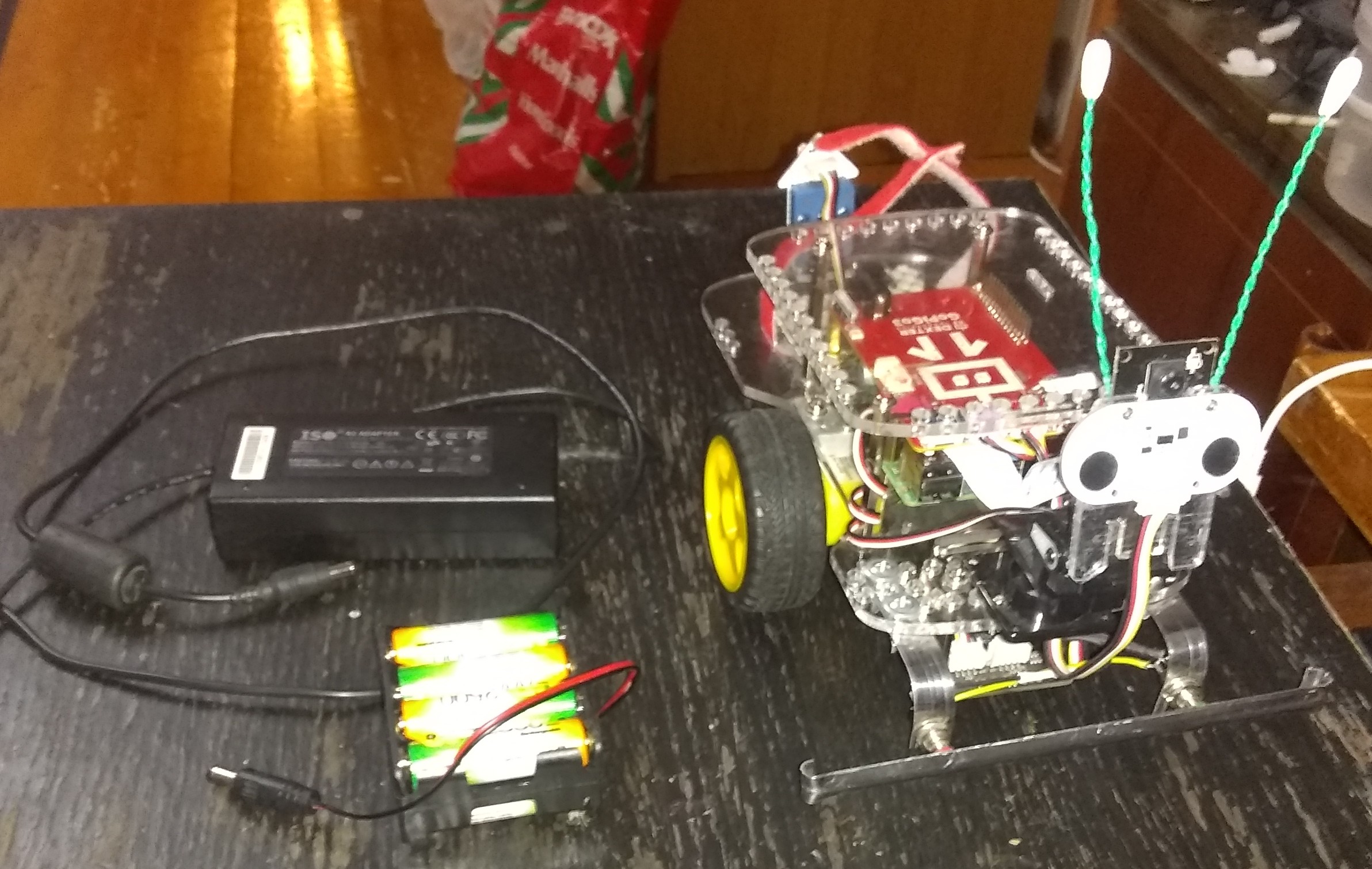
To substantiate my feelings and to back them up with facts, I took a DHT22, glued it under the cover plate but above the GoPiGo3 board and carried out some measurements.
Here is a picture of the installation:

And here are my results:
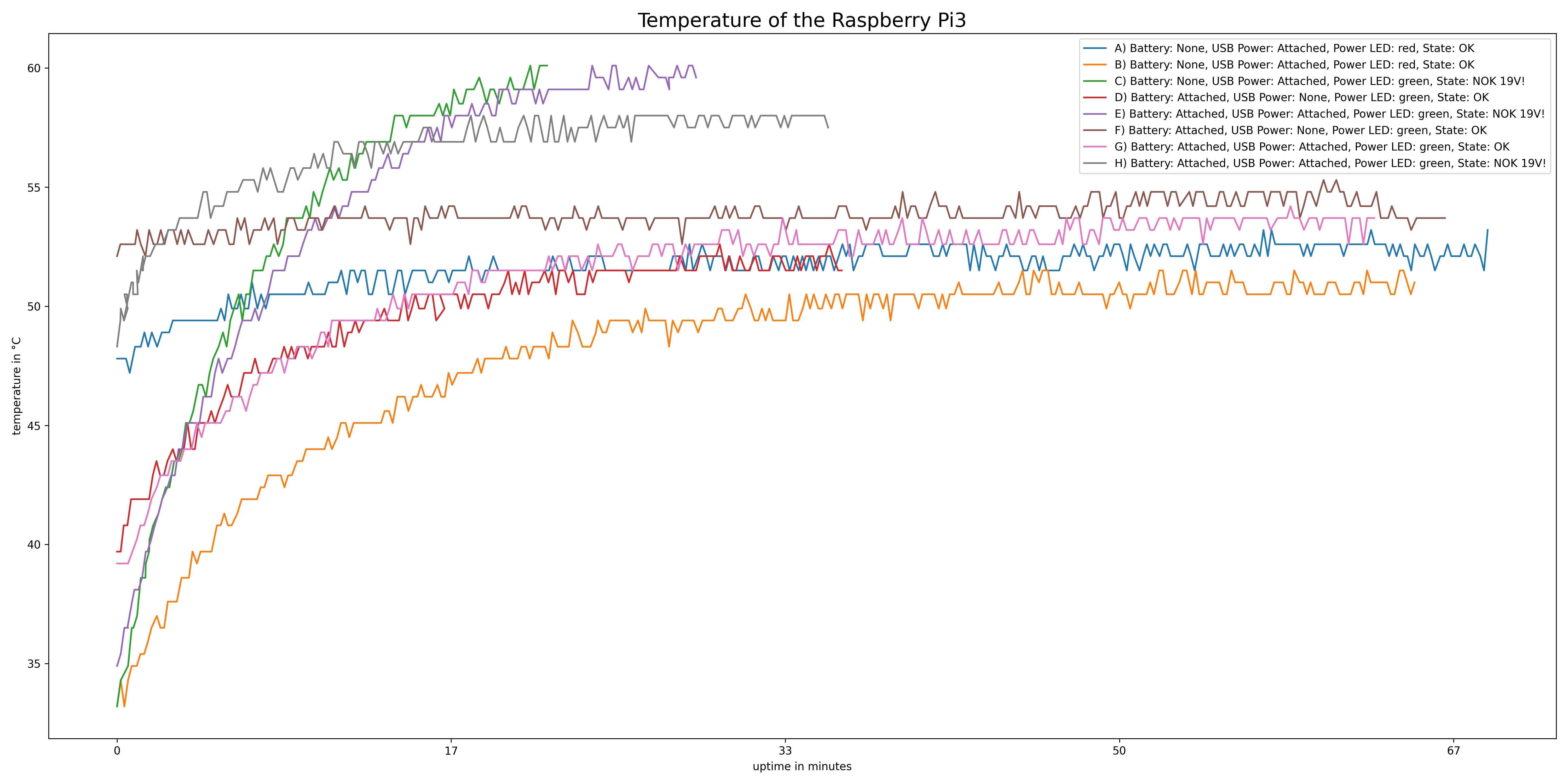
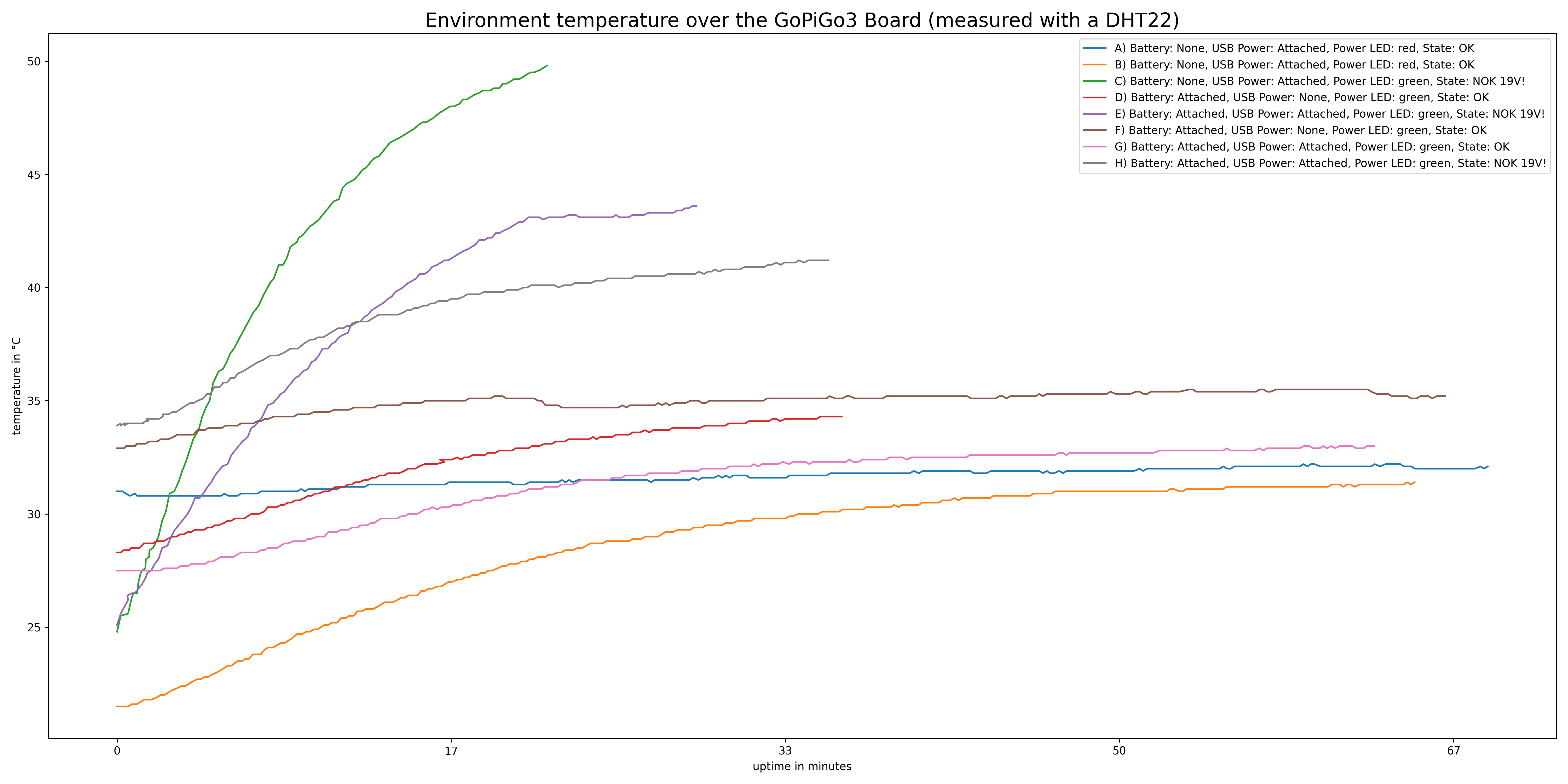
You can clearly see that when the whole thing gets into a state in which 18-19V are reported, the heat development is greater than usual.
I switched off the Raspberry pi as soon as it starts to throttle, here an example of the last entry in the data for the case C):
18:31:24 up 22 min, 3 users, load average: 0.19, 0.18, 0.11 | temp=60.1'C | volt=1.3438V | frequency(45)=1400000000 | throttled=0x80000 | Temp=49.8*; Humidity=28.4%; | Battery voltage: 19.557; 5v voltage: 4.921; Dexter Industries; GoPiGo3; ...; 3.x.x; 1.0.0; |
During the measurements nothing ran on the Raspberry Pi / GoPiGo, it just stood there and did nothing, except produce heat.
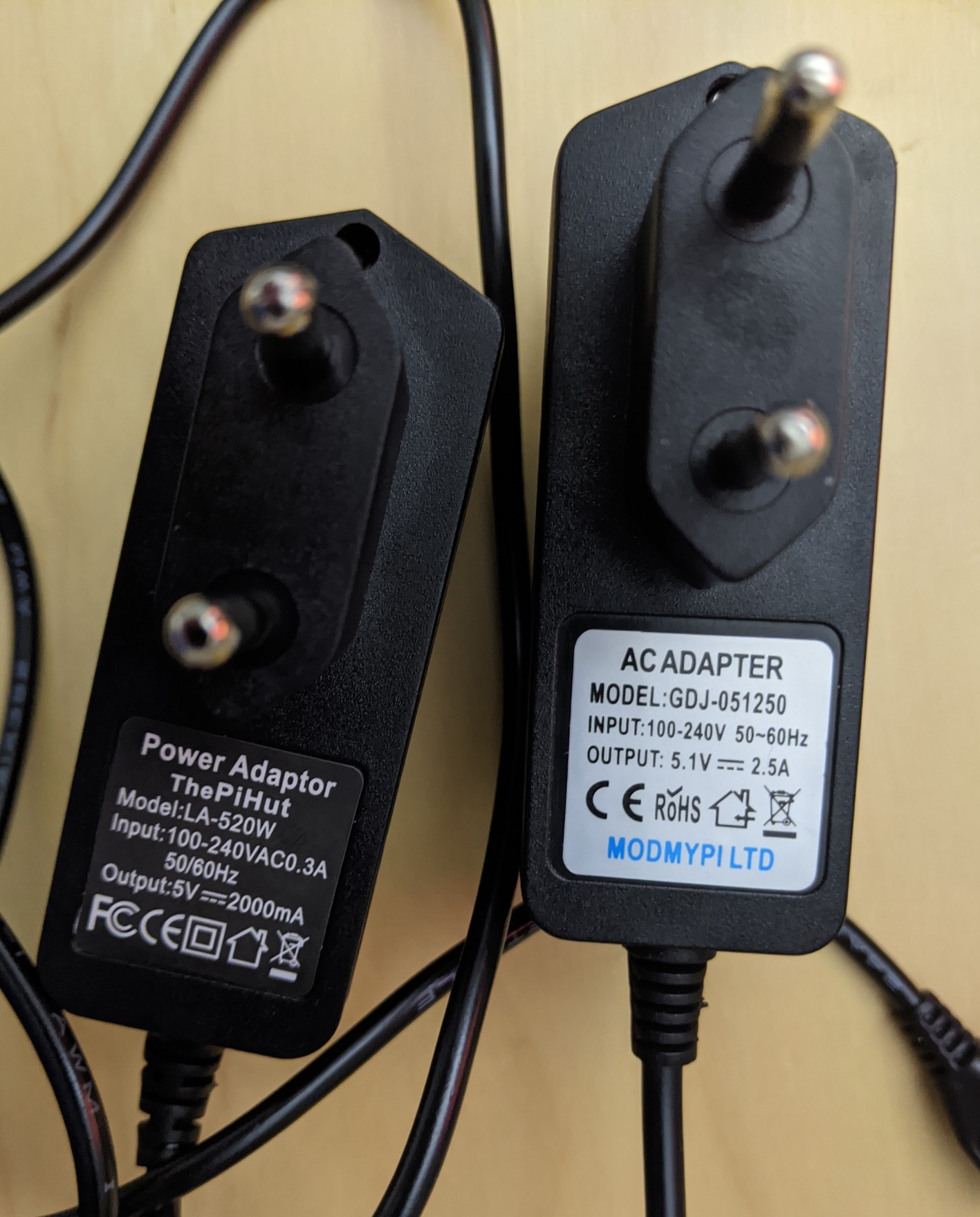
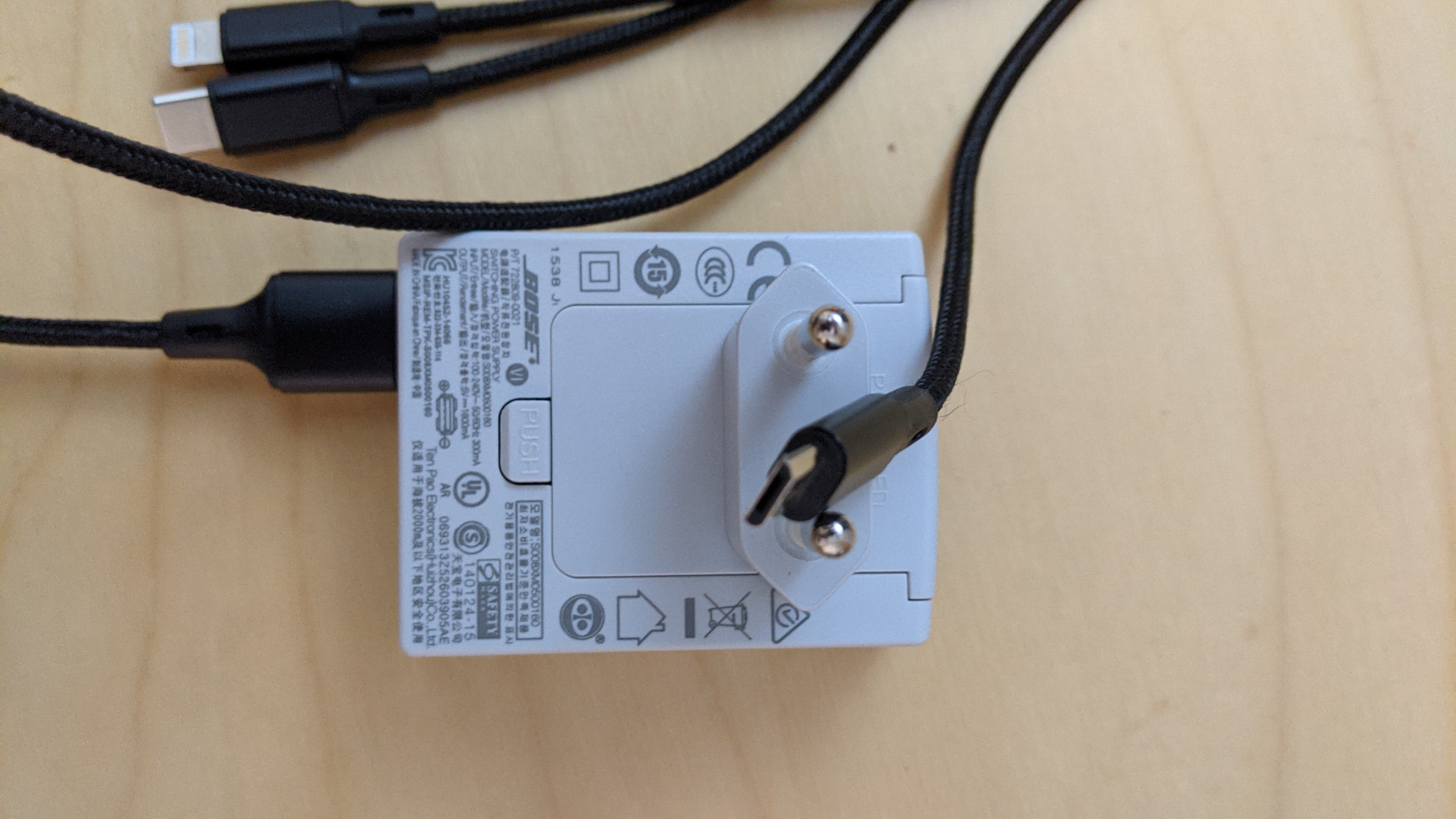
And to be sure that there is no problem with the usb-power-supply, I tested two of them:
And now for the other bad news: I received a second GoPiGo3 this week, exactly the same board (v3.3.0).
I have now tested whether this has the same behavior and unfortunately yes - even with that I sometimes have a status in which 18-19V is displayed and it is heating up.
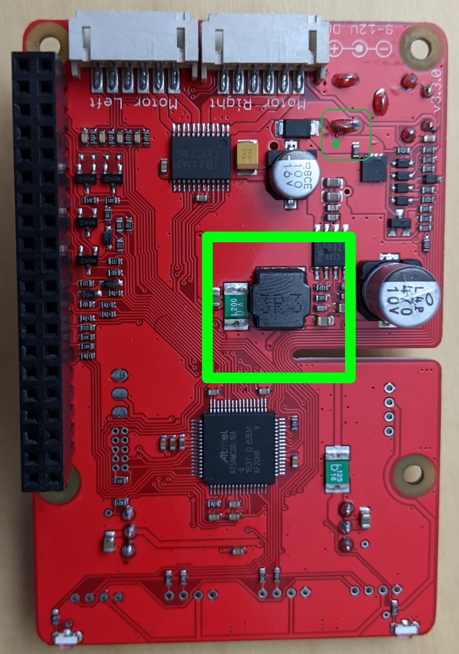
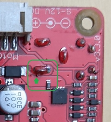
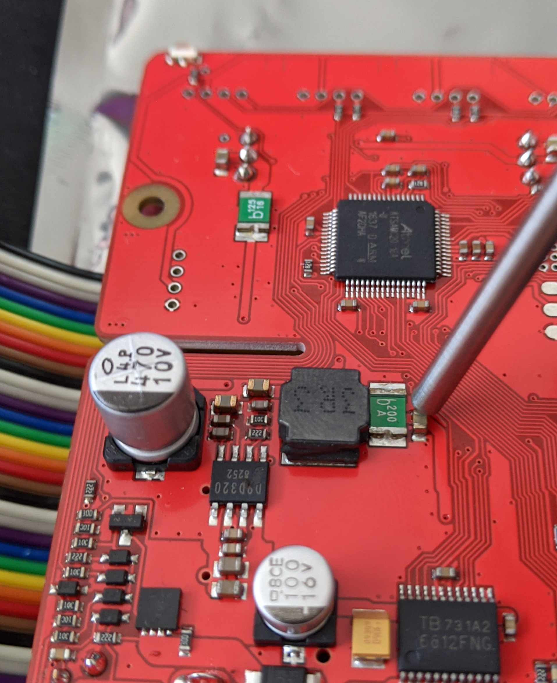
To make matters worse, this board has now stopped working. I don’t know what happened, but there was a smell of burning and I immediately cut the power and removed the battery. If I now plug in the battery, nothing happens and the board can no longer be switched on. But if I put the board on a Raspberry Pi and feed the Raspberry Pi with a USB power adapter, the power LED flashes and the board seems to start. BUT after a few seconds a part on the board heats up so much that I switch it off again because it’s just too hot and I don’t know what’s going on. The part that heats up so much seems to be the one marked in green:

Now I have to ask the support what I can do and whether I can get the board replaced (or maybe both). I would also be happy if the support could check the board (maybe also my other one with the heat problem) - I don’t know what I could do wrong  or whether I just have bad luck.
It’s a little bit frustrating because the product is very cool! I have chosen this robot for my semster thesis which should be finished in one month - but I lose a lot of time with the heating problem.
I will now write to the support and hope they can help me out.
One last question: One last question: Nobody here has exactly the same board (v3.3.0) and the same problems?
3 Likes
This is extremely interesting.
Do you mean the large square shaped part labeled “3R3”?
That’s the power supply regulator filter inductor and there’s no real reason for that to get hot absent a drastic short circuit somewhere.
IC-1 is the power regulator IC. Does it get hot? How about the two big silver capacitors?
Frankly, without sitting down with you and looking at that with meters and tools, I honestly don’t know what to say.
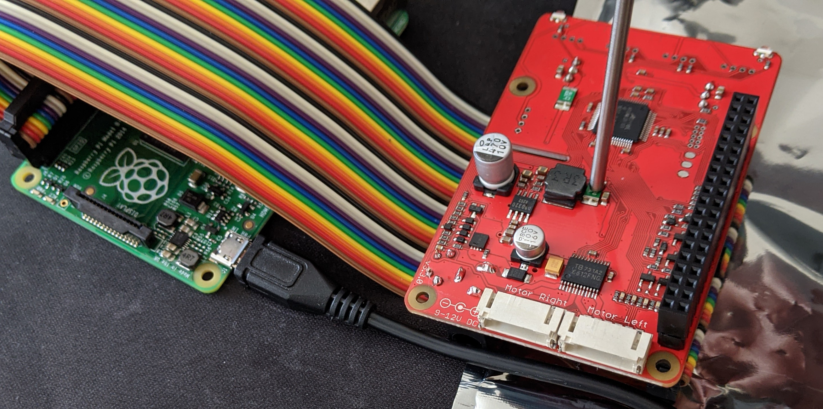
Have you considered connecting the pi to the controller board with a 40-pin ribbon cable?
I hesitate to suggest this, and didn’t suggest it before, because it’s really easy to get the pins flipped and potentially fry both controller and pi.
If you are confident enough to try this, and carefully see what parts are getting hot, that would be very helpful.
Also, have you tried a different Pi?
One last thing I forgot to ask:
With the two halves assembled, have you looked for accidental points of contact between the two boards?
What if the two motors are disconnected from the controller?
Do you have anything else plugged in?
You really have my total attention with this!
I wish I could be there with you to help figure it out.
I was examining your board with a bit of magnification and I noticed something potentially interesting that looks like a solder-splash across two power traces near the upper right of your picture.
Viz.:
Full size:
And a cut-away
Does that exist on both boards? Is this board still working? If so, would you flick it off and see if that eliminates the problem?
For comparison, here’s a magnification of the original board pictures you showed me. You will notice a much better, and cleaner, soldering job done to that pin.
A couple of other things that confuse me:
Viz.:
According to the schematic I have:
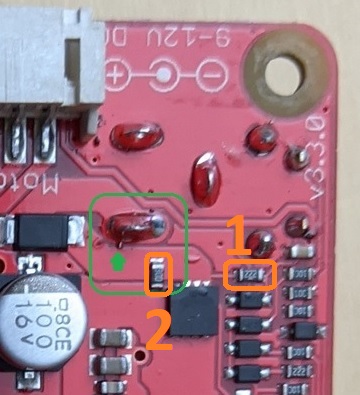
- item #1 should be a diode, not a 22k resistor.
- Item number 2 should be 200k, not what looks like 30 ohms. (“300” in resistor notation should read as 30x100, in other words, 30 ohms. The other, reading “222” should read as 22x102, in other words 2200 or 2.2k - the last digit being the “multiplier”, or the number of zeros to append to the two numbers that represent the value.)
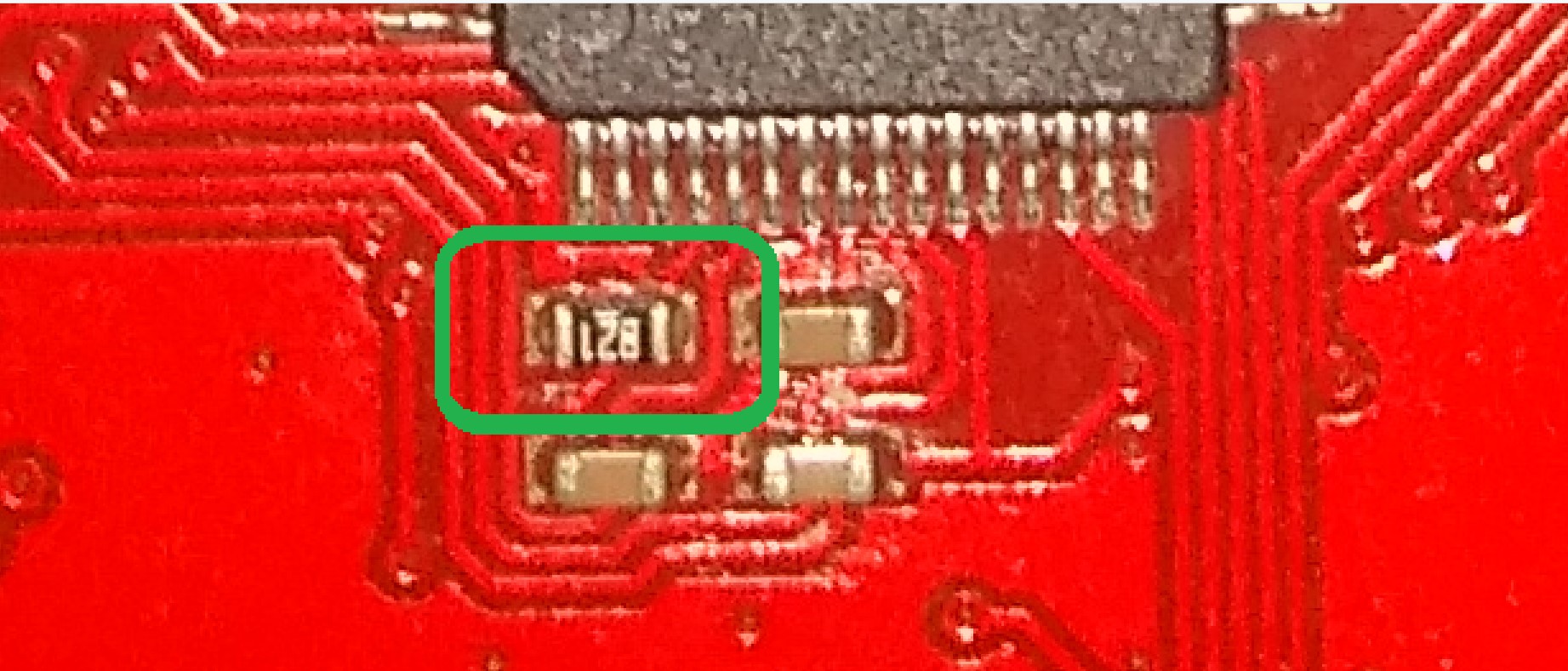
Note also that my PCB, which is an older version GoPiGo-3 board has the same 30 ohm resistor there.
For comparison, look at the 820 ohm current limiting resistor leading to pin-4 of the Atmel controller chip, (5v Vref). It is labeled “821” which equates to “820” ohms.
My schematic, which is marked as the GoPiGo 3.2.0 version, shows completely different values for a lot of the components in the power supply and power management sections.
Note that, aside from the resistor in place of the diode, your boards components look just like mine, except for the placement of CP14, the very large silver electrolytic capacitor, which on your PCB was moved to the edge of the board.
Here’s that side of mine.

You will notice that I have moved CP14 to more closely match the location of it on the new PCB so that it will fit the heatsink and fan on the Pi-4.
Have there been any electrical/component changes in the GoPiGo PCB that aren’t reflected in my version 3.2.0 schematic?
How difficult would it be to ship a latest-rev controller board to Moscow Russia? This might need a bit of closer examination of the hardware.
1 Like
I checked the soldering and cleaned that, but it did not help.
Pictures of the dead board:

And the working (apart from the heat problem when not only using the battery pack):
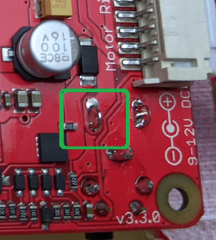
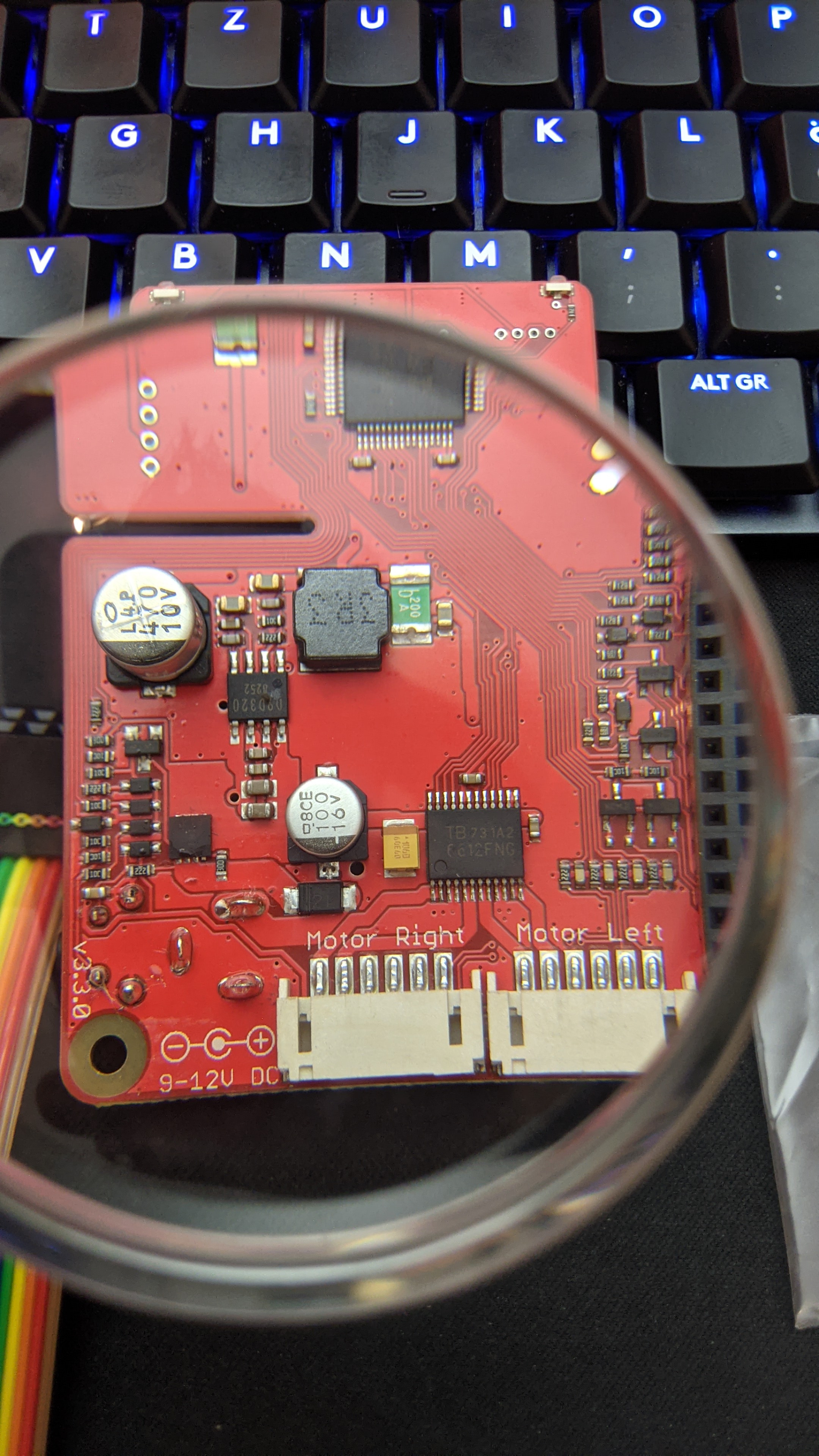
I found a cable and could run with boards separated. The 3R3 is not the one heating up on the dead board, it’s in this area:
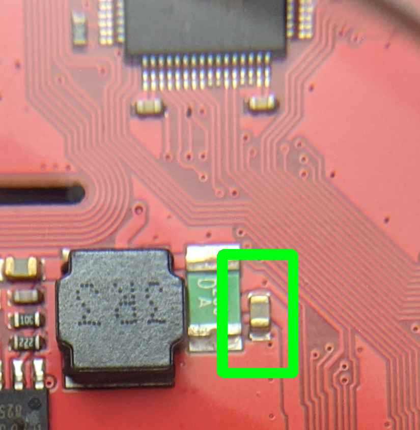
When I check it with my fingers, it’s one of the two next to the 3R3, would say the little one (in the green box). And a few seconds it’s normal and then it heats up very quickly. If I know what could happen I would let it run… i have no idea about it and i’m a bit scared.

1 Like
Is it the bigger green part or the tiny brown one?
Can you get me a nice, clear, square-on picture of the other side?
Do you have a can of compressed air like "Dust Off?
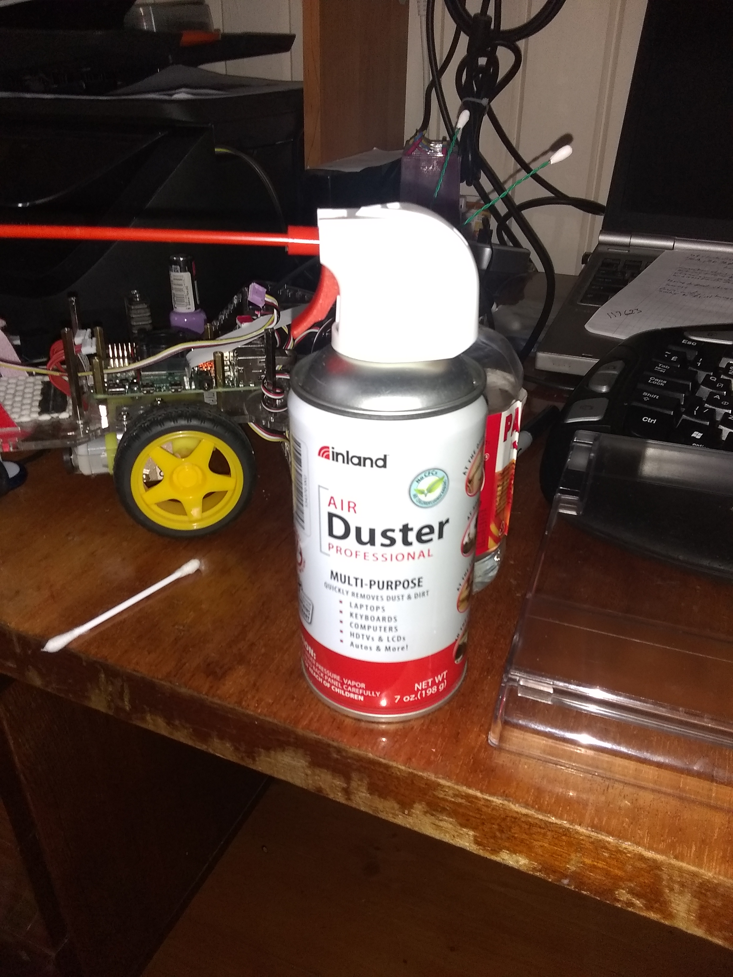
Here’s a trick:
Hold the can upside down and spray the cold liquid on the board all over that area. Do it a couple of times. Get it nice and frozen. (Be careful of the IC’s)
Then turn it on with both supplies and see what warms up first.
1 Like
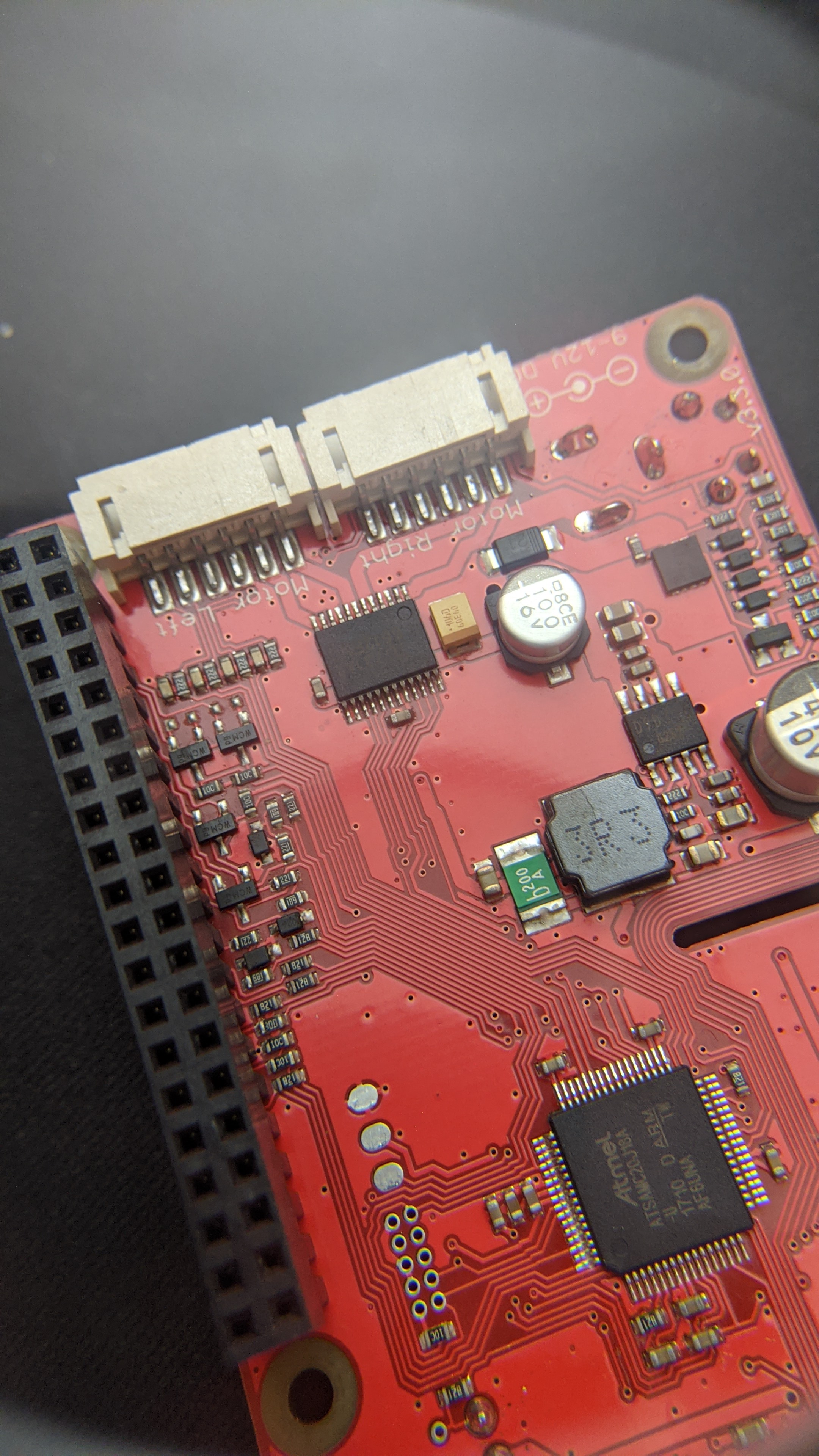
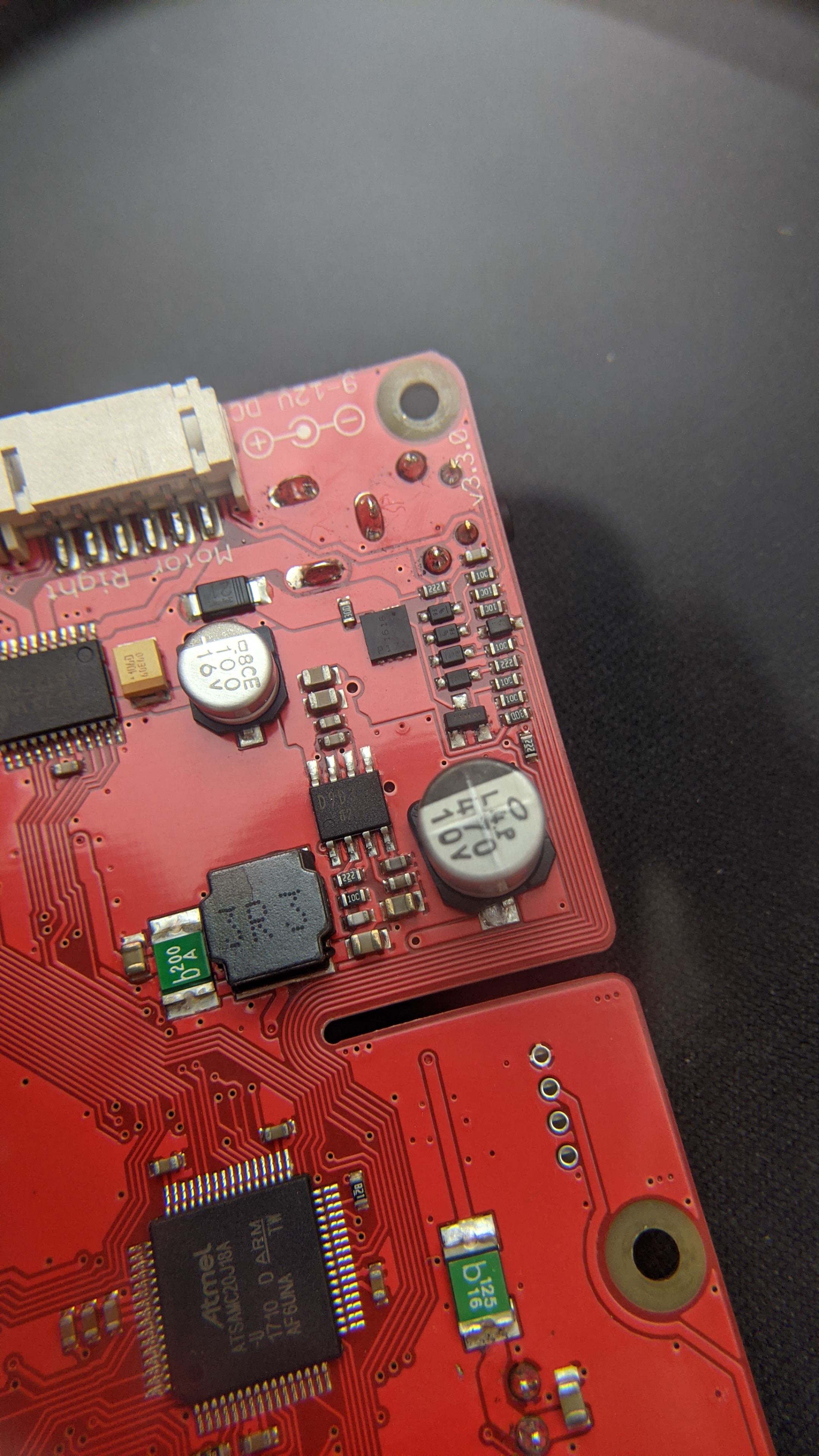
@jimrh Here a picture from the other side (hope it’s clear enough - aks if you need a cleaner picture of something else or a sector of it):

I have no can of compressed air and the picture I’ve send is from the dead board. I would like not to lose my warranty at the moment (for both boards). The other board works (with batteries only) and I hope I don’t lose that too because I have to go forward with my semester thesis - no experiments on the board that runs actually until I have an alternative. But if I have an alternative/solution, I would be very happy to give you the informations and do further investigations.
I have contact with the support (@mitch.kremm) and hope they can help me out somehow.
I thought I could order a new one from a shop here in Switzerland, but if they send me the exact same version (v3.3.0) again, I don’t know if I would have the same problems.
Thanks for your help!
2 Likes
Do they have PCB artwork documents?
Can you tell me which of the two small parts are getting hot?
I know only this documents https://www.dexterindustries.com/GoPiGo/learning/hardware-port-description/ with an older revision v3.1.3.
I tried to measure which component it is (on the broken board!), don’t know if this measurement technique is good…
Measured with this:
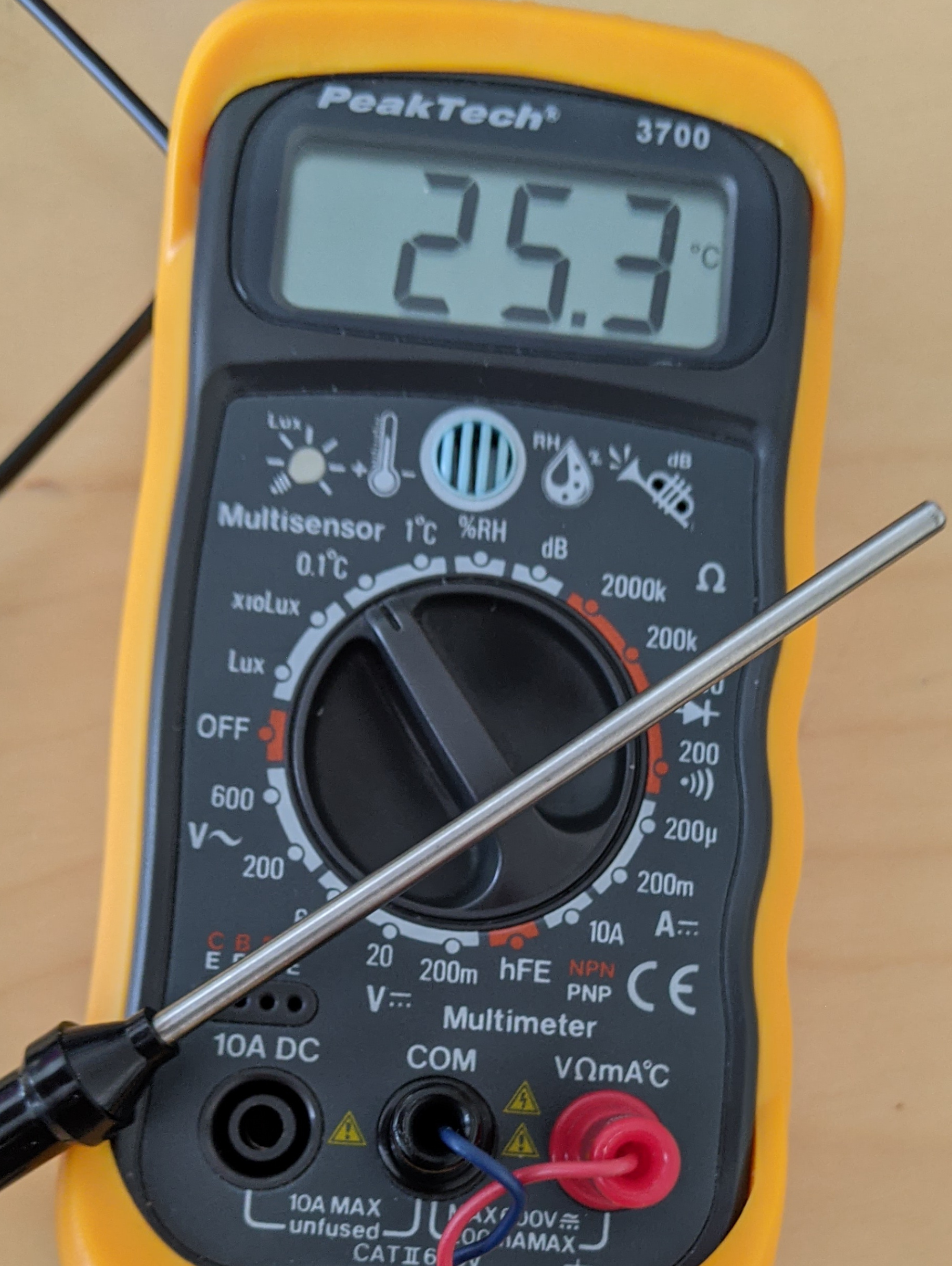
Started the Pi and let it on for 1 minute.
This one was gone to 40° in the minute:
And this one was gone to 31° in the minute:
When this technique for such measurements is ok, then it’s definitely the green one heating up.
And I saw this documents https://github.com/DexterInd/GoPiGo3/tree/master/Hardware, but the revision I have is missing there too.
2 Likes
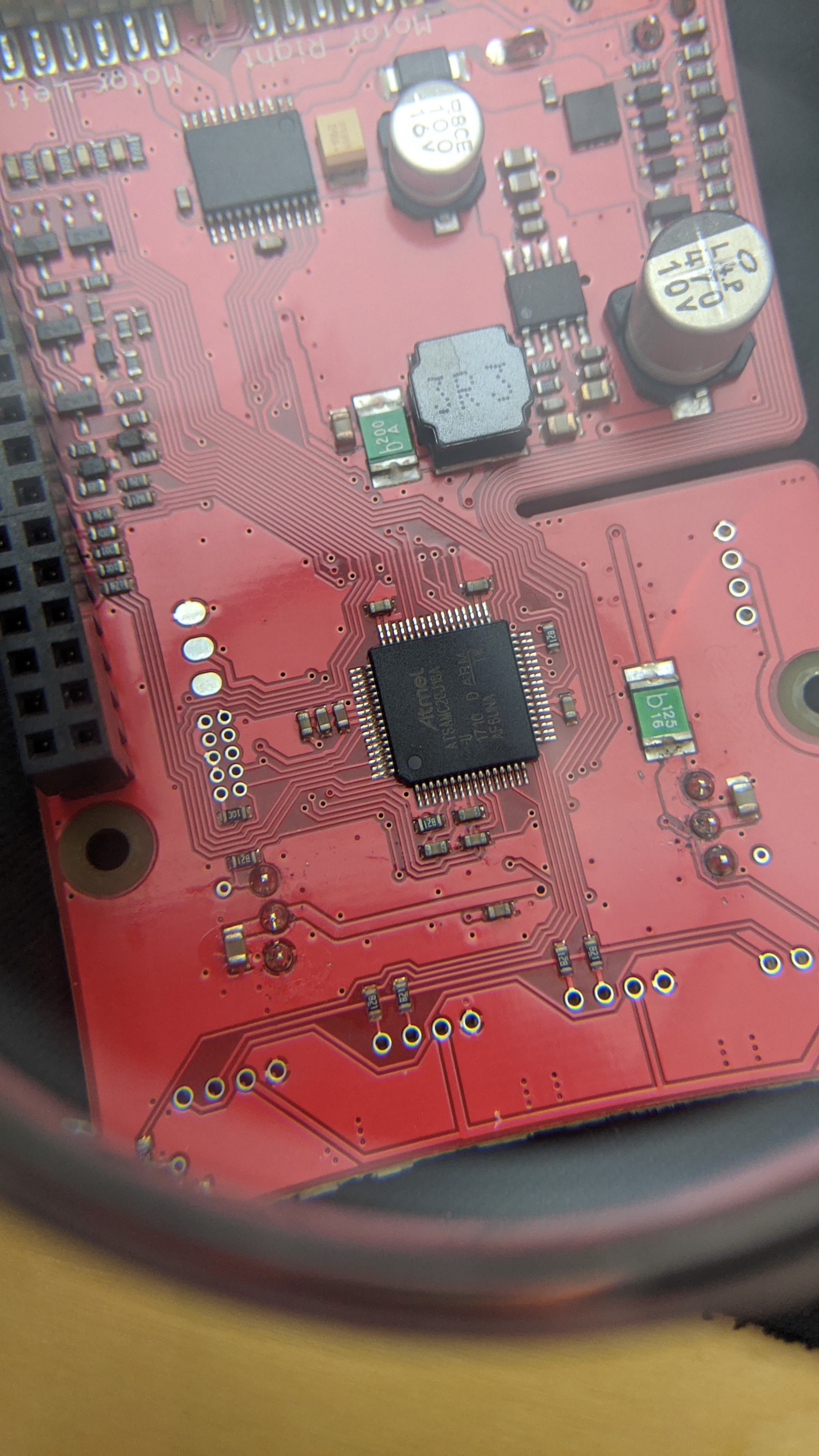
That green part is a soft (self-resetting) fuse. There are two on the board. One there that feeds the battery power to the PI if nothing else is connected, and another one closer to the Atmel processor for the servos.
It should NOT get hot.
Please make the following tests on the working board.
Test:
- Hook things up so that the component gets hot.
- Remove the power adapter from the Raspberry Pi itself.
Examine: Does the green component start to cool off?
Can you check the voltage on each side of the green component when it gets hot?
Given the following illustration:
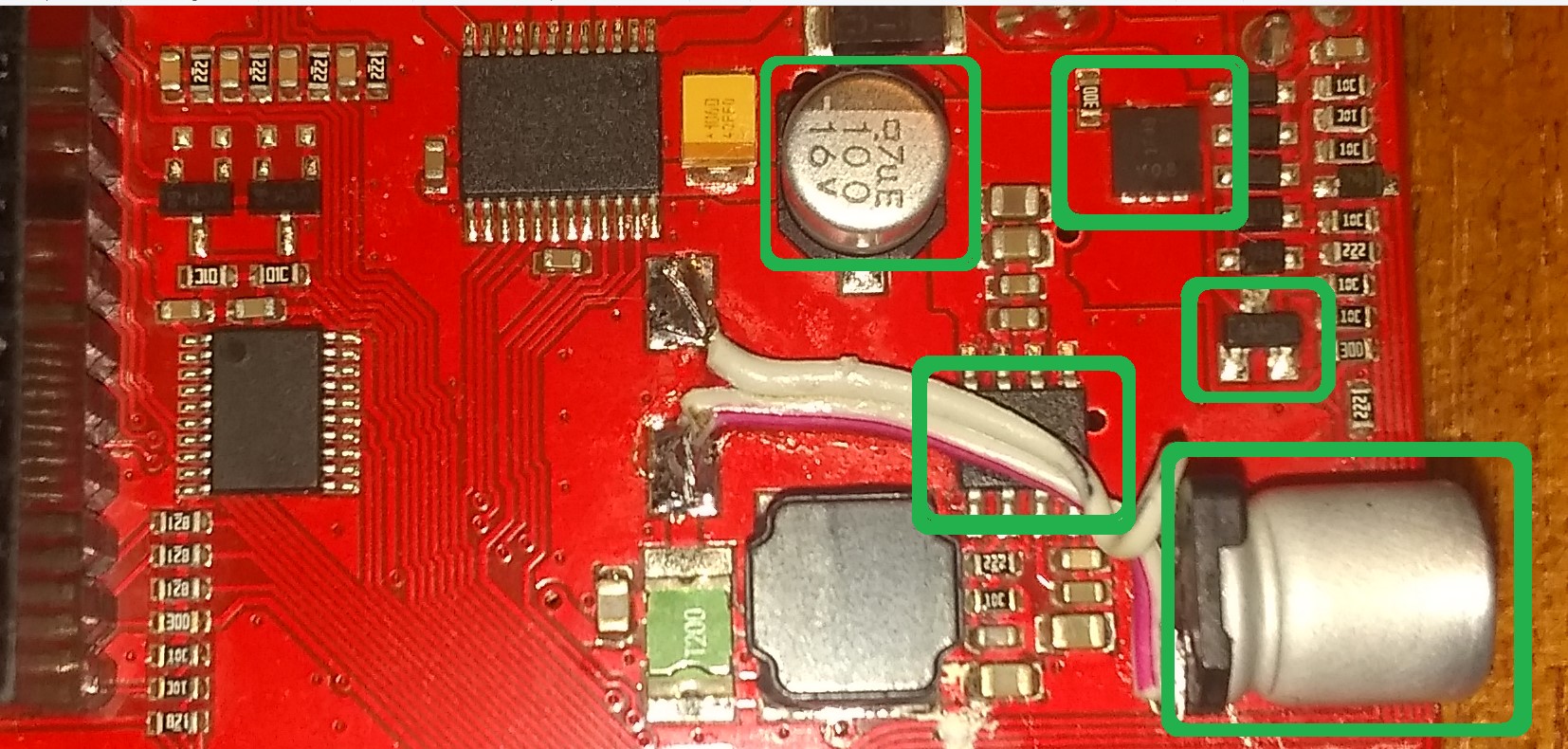
Would you please check if any of these additional components get hot?
(Note that this is my board, but you should be able to figure it out.  )
)
Switzerland? Damn!
Well, at least we’re on the same side of the pond. . .
Pity you aren’t closer, I"d drive over, bring some stuff, and we’d hammer this thing in a few hours.
Nice meter! Where did you get it?
Jim, Woody told you he needs to protect that working board, like critical to his course. I suggest that he not mess with it, period. Every handling of these boards is an opportunity for “bad juju.”
A long time ago, in a far away land (New Mexico State University 1976), I decided to do a one-semester research project to complete my Mechanical Engineering degree with a “never got less than an A in his life” study buddy.
We submitted a plan, requesting funding from the department for the material, and got approval by our graduation review adviser. It turned out the advisor was in a lawsuit with the university, and the university would not approve the funding. We submitted a change from physical analysis to software simulation analysis, which the review advisor would not approve, and would not release us to a different advisor.
Being the final semester before graduation there really was not time for anything to go wrong. I had invested six years of course work, and I really wanted to stop paying for life and start earning a living.
The university agreed to switching advisors, allowing the software simulation analysis, and we managed to graduate as planned.
Just sayin’
2 Likes
I’m here all the time the next coming weeks because of covid-19, you can come here immediately - but think it would not be easy to travel over borders (…covid-19 ).
Thank you very much for your help! Really cool to have such a community here! But now I have to prioritize my things a little and the highest one is to go forward with my work. I asked the support for warranty exchange, but they are in the US and it’s not so easy to do that in a fast way. Depending on there response I will try to get some replacements from the shop I bought the two GoPiGo3s here in Switzerland.>
If I get the chance to do more research on this problem after my semester thesis progress is a bit further than now, and I wouldn’t break my warranty claim with experiments and I have a backup in place, then I would love to do further investigations.
Bought the meter from here: https://www.neukom-electronic.ch/index.php/messtechnik - long time ago
2 Likes
Absolutely true.
My skill-set in a nutshell:
- Programming skills: Minimal.
- Social skills: Abysmal.
- Hardware skills: Phenomenal.
My kid brother has to periodically remind me that “other people aren’t as good at this as you are”, and I totally agree. I would have no problems experimenting with the last bottle of oxygen while waiting for rescue. Others, maybe not.
Of course Woody has to prioritize and make sure his studies are successful and I am sorry for not paying attention.
I think I would express that “slightly” differently, as in:
(…covid-19  )
)
Absolutely true.
You are totally correct and I apologize for my thoughtlessness. ![]()
Using an external power adapter, (at least with an earlier revision GoPiGo controller board), is a normal use-case.
If you can do that and it doesn’t get hot, that’s fine. If you are concerned that it might damage the robot, then (of course) continue using the batteries. Hopefully you have lots of spares.
Since I am also doing a LOT of development work with Charlie, involving minimal or no independent movement, I also attached a 12v 2+ amp power adapter similar to the one you showed earlier.
Re: The high-frequency tone.
That might be coming from the adapter. If you are confident that it’s coming from the robot itself, I’d either use a different adapter or continue using batteries.
Re: Development on the robot itself.
Especially if you are using batteries to power the 'bot exclusively, I would recommend doing development externally, and then moving the files to the 'bot for testing, which is what I am doing with my remote camera robot project.
What I do:
I have a PC running Windows 10, and I’ve downloaded Visual Studio Code to my system. I also set up a GitHub repo to store my work off-line. Visual Studio Code handles all the “Git” stuff for me so all I have to do is push and commit.
Once I have something I think worthy, I use FileZilla to move the file(s) to the 'bot for testing.
If I’m going to be spending a lot of time coding, or if I am working on just the browser side of my project - and I can simulate that entirely on my PC - I don’'t even turn the 'bot on.
Of course, you have to do things the way that works best for you.
For your information: I found an old gopigo (v1.6.0) in my cellar (didn’t know that I still have it).
I’m now working with them until my other (newer) boards are back (hopefully soon).
I can work as expected with v1.6.0, using the same battery pack and the same usb power adapter as with v3.3.0 -> I can switch between battery and usb power adapter as I want and use both at the same time and it works perfectly.
When I get the new v3.3.0 boards back, I will try the rpi2B board with the v3.3.0 board and check whether the problem also exists there. But I hope that with the new boards the problem is completely gone.
The differences I have to the configuration with the heat / 19V problem are:
- Board is v1.6.0 instead of 3.3.0
- Raspberry pi is a Rpi2B instead of Rpi3B +
2 Likes
Hi, I received a brand new GoPiGo3 Base Kit last week. It seems that the board has the same problem: It shows me 19V when I do this:
-
Get a sd-card with raspbian for robots stretch and plug it into the raspberry pi
-
Connect the raspberry pi with the GoPiGo3
-
Attach the battery pack
-
Press the power button on the gopigo3 board
-
Wait until the rpi has started.
-
The power led on the gopigo3 should be green
-
SSH to the raspberry pi
-
Execute
sh ~/Dexter/GoPiGo3/Troubleshooting/all_tests.sh
Result:
pi@dex:~ $ sudo sh ~/Dexter/GoPiGo3/Troubleshooting/all_tests.sh
===============================
GoPiGo3 Troubleshooting Script
===============================

Checking for hardware, and checking hardware and firmware version.
==================================================================
Manufacturer    :  Dexter Industries
Board           :  GoPiGo3
Serial Number   :  6EE2126A514E4C47324B2020FF041911
Hardware version:  3.x.x
Firmware version:  1.0.0
**Battery voltage :  10.768**
5v voltage      :  5.049
-
Attach now a usb power supply to the raspberry pi.
-
The power led on the gopigo3 should be green
-
Execute
sh ~/Dexter/GoPiGo3/Troubleshooting/all_tests.sh
Result:
pi@dex:~ $ sudo sh ~/Dexter/GoPiGo3/Troubleshooting/all_tests.sh
===============================
GoPiGo3 Troubleshooting Script
===============================

Checking for hardware, and checking hardware and firmware version.
==================================================================
Manufacturer    :  Dexter Industries
Board           :  GoPiGo3
Serial Number   :  6EE2126A514E4C47324B2020FF041911
Hardware version:  3.x.x
Firmware version:  1.0.0
**Battery voltage :  19.026**
5v voltage      :  5.081

Log has been saved to Desktop. Please copy it and send it by email or upload it on the forums
-
Remove the battery pack
-
The power led on the gopigo3 is still green! (Should be red! Motors should be blocked if no battery pack is attached, but led is still green and motors could be moved… on the v1.6.0 board, the motors are blocked like expected)
-
Execute
sh ~/Dexter/GoPiGo3/Troubleshooting/all_tests.sh
Result:
pi@dex:~ $ sudo sh ~/Dexter/GoPiGo3/Troubleshooting/all_tests.sh
===============================
GoPiGo3 Troubleshooting Script
===============================

Checking for hardware, and checking hardware and firmware version.
==================================================================
Manufacturer    :  Dexter Industries
Board           :  GoPiGo3
Serial Number   :  6EE2126A514E4C47324B2020FF041911
Hardware version:  3.x.x
Firmware version:  1.0.0
**Battery voltage :  19.103**
5v voltage      :  5.085

Log has been saved to Desktop. Please copy it and send it by email or upload it on the forums
-
Reattach the battery pack
-
Remove the usb power supply from the rasbperry pi.
-
Execute
sh ~/Dexter/GoPiGo3/Troubleshooting/all_tests.sh
Result:
===============================
GoPiGo3 Troubleshooting Script
===============================

Checking for hardware, and checking hardware and firmware version.
==================================================================
Manufacturer    :  Dexter Industries
Board           :  GoPiGo3
Serial Number   :  6EE2126A514E4C47324B2020FF041911
Hardware version:  3.x.x
Firmware version:  1.0.0
**Battery voltage :  10.819**
5v voltage      :  5.045
The engineers in US (thanks @mitch.kremm ) could not reproduce the problem. He asked me to test with other USB power supplies, here are my results:
These Adapters/Cables shows the result above with the 19V:
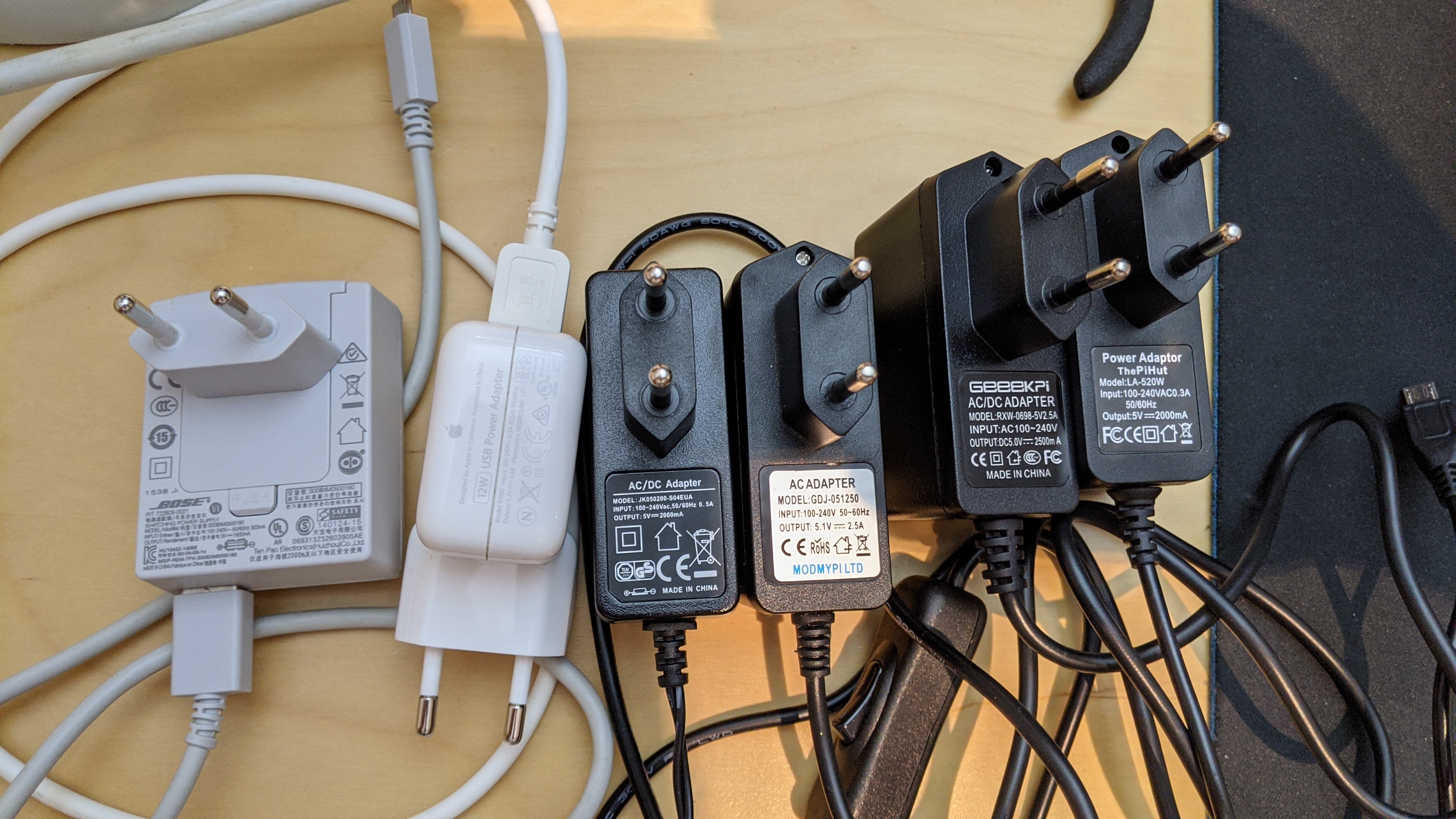
This combination works not as expected, shows 8V with the power adapter only and doesn’t block the motors (should be blocked without battery pack):
Only the following powerbank or adapter works as expected, also working when I power the usb port of the raspberry pi from something like this https://www.powercubes.eu/de/produkt/powercube-extended-usb-ac-wirelesscharger/.
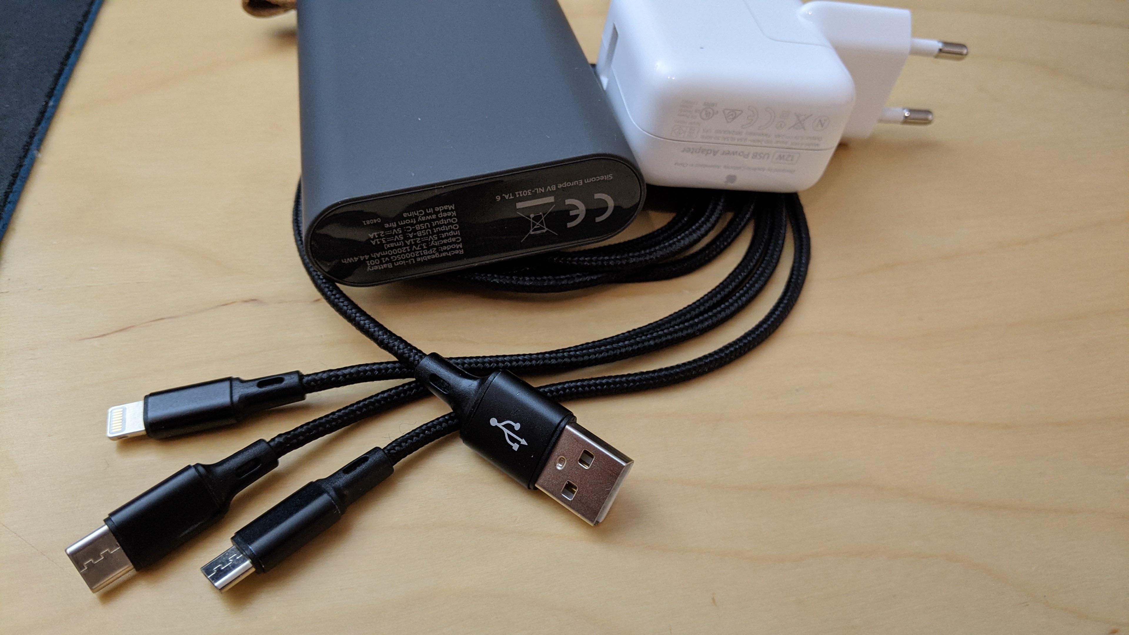
I’ve been working with these adapters for a long time with different Raspberry Pis in combination with different boards and had never such a problem with one of them. I can not believe that so much adapters should have a problem. With the GoPiGo v1.6.0 the adapters are all working without showing me such high voltage!
Nobody out there in Europe (maybe 50Hz) has the same problem with a GoPiGo3 v3.3.0 board???
1 Like
I have the older v3.2 “red” board, and can confirm that
when:
- The board is powered by both +12v and +5v at the same time.
—and— - The power supply LED is lit green.
—and— - The +12 supply is subsequently removed.
THEN
- The green power LED remains lit.
- The wheels attempt to turn when commanded despite the absence of the +12 volt supply.
- I don’t remember exactly about the power supply reading, (mine maxed at about 14.4 volts), but I think it remained high.
I remember mentioning this in earlier postings of mine discussing the operation of the robot from about a year or so ago.
The +5v supplies are all “Element-14” or other officially-branded Raspberry Pi power supplies purchased from Micro Center, a reputable and official retailer. (With US power pins. I use an adapter to connect to the two-pin European power pins shown in Woody’s illustrations.)
Also note that I have several of each kind - both micro-USB and USB-C connector supplies, all official supplies, for both the Pi-3 and earlier and the Pi-4
All of the micro-USB +5v supplies I use for my Pi-3 (or earlier boards), are “official” Pi-3 rated supplies.
The +12 supplies I use are either:
- A bank of eight NiMH cells in the provided holder.
- A 12v 3A supply originally intended to be used with a high-current-draw device like a NAS box or an external hard drive. Measured ripple, (using the “AC” scale of my multi-meter across the open end of the 12v barrel connector), is in the magnitude of micro-volts.
Hardware:
These tests were done using either a Pi-3B or a Pi-4B-4 gig, using stock “Dexter” Raspbian for Robots or DexterOS releases as of those individual points in time.
I am using an “as shipped” 3.2.2, (early version with C14 in the middle of the board), GoPiGo-3 board using the stock 1.0.0 firmware.
I only use known, and verifiably good, SD cards. (i.e. SanDisk Extreme Pro, application grade A1 or A2, or equivalent Micro Center SD cards)
Modifications:
I have recently updated many of the Pi boards dedicated for GoPiGo use, (or other uses), with Adafruit Real Time Clock modules, and have made the appropriate modifications to the config.txt and hwclock.cfg configurations to enable them.
However, these findings predate these updates, but persist through them.
I would like to help you get to the bottom of this too.
Would you please be kind enough to publish the specifications of the system you are trying to duplicate this with?
- What version of GPG board? Are you using the as-shipped stock 1.0.0 firmware, or something special being used internally?
- What version of Raspberry Pi are you using, and if it’s a Pi-4, what firmware revision are you loading?
This can be significant. Ask Nicole about the headaches we’ve been having flashing firmware with the Pi-4!

- What operating system, version, and any special modifications/installations, (for development work, etc.), are you using?
- What is the kernel version reported by “uname-a”?
My system returns
Linux Charlie 5.4.79-v7l+ #1373 SMP Mon Nov 23 13:27:40 GMT 2020 armv7l GNU/Linux
where the “armv7l” indicates the stock 32-bit low-latency kernel) - Can you reproduce this on an absolutely stock, as-shipped, system with as-shipped hardware, etc.?
I can honestly say that in the, (literally), decades and decades and decades of hardware and software testing I have done, places where the developers say “I can’t reproduce it.” or “It works perfectly for me!”, invariably turn on something that either the user, or developer, did differently.
I’m not trying to bust chops, but once we know what the differing factor(s) is/(are), we can figure out what’s really going on.
@woody123, if I might offer a way for you to proceed on your project without getting derailed by the issue you have discovered.
One way that users develop for the GoPiGo3 is to only use battery power, and put the robot “up on blocks”, on the desk on a block of foam to allow the wheels to turn without the robot walking off.
While it is good for users to take a break periodically, (like while recharging the battery pack), some keep a spare battery pack always recharging so there is no real “down time”.
Perhaps you don’t need to solve the dual-power-gets-hot issue?
2 Likes
. . . or, do what I do.
If I don’t need my 'bot to be moving while I am working on it, I use a +12v adapter and plug it into the battery connector. (99% of the time this is what I do while working on programming projects.)
If I need to test something that involves the 'bot moving around, I plug in the batteries. I also have several extra sets charged up and ready to go if I need them.
If I’m programming, and need a “quick” motion test while on the +12v adapter, I either pick Charlie up and watch the wheels or use a piece of wood to lift him up off the table for the couple of minutes I need to see what’s going on.
This avoids all the “dual power” issues for the time being.
Later on, after you have totally dominated your class project and gotten top marks, (and I can dig up a newer version of the GoPiGo controller board), we can revisit this issue.
For now, get your project going. We’ll pick up the rest later.
2 Likes
Yup. The trick is figuring out what’s different.
I attempted to reproduce this again yesterday.
I used our official LiOn battery and the official Raspberry Pi charger on a Pi3+ / GPG 3.3.0 board.
I’m in Canada, so 60hz, 110V although the charger should take care of removing those differences.
I couldn’t reproduce the issue.
We also did the same right in China (50Hz, 220V) and he couldn’t reproduce either.
So we’re still looking for the magic sauce.
2 Likes