A new (ahem!) "128x64" OLED display for Charlene

My big problem with my robots is getting them to communicate with me if and when they need to.

@cyclicalobsessive solved this problem, (very cleverly and nicely, I might add), by attaching voice modules and speakers to his 'bots.  With that, his robots can “ask for help” whenever they have a problem.

Unfortunately, everyone else in my house has a spite again’ any extraneous noises - even me thinking out-loud or listening to music drives them absolutely BONKERS!

Also, I’m not as comfortable as @cyclicalobsessive is with the idea of letting robots wander the house aimlessly, waiting for the opportunity to get under foot or trip someone.  (I can trip over my own two feet, all by myself, no help necessary, thank you very much! :man_facepalming: )

So, I decided that a visual display was the best option.

But that has its own set of problems.

Displays, (aside from remote displays), can be divided into four broad categories:

  1. Displays that plug into the Raspberry Pi’s display port connector.

  2. Displays that plug in to the GPIO connector and communicate via SPI.

  3. Displays that plug into the GPIO connector and communicate via i2c.

  4. Other displays that use a serial connection, or plug into a HDMI port, etc.

Then there’s the question of size.

  1. Display-port and HDMI displays are large, power-hungry, and expensive, and I don’t want a display that’s too large to mount flat on a robot’s back.

  2. Other displays are either too large or are so tiny that they can’t be ready without a magnifier.

That leaves us with either e-Ink displays or small TFT/LCD/OLED displays and a choice of interface.

  1. The e-Ink displays are a very good especially as they come in a variety of sizes and configurations, they’re high-contrast displays, they sip power through a carbon nanotube and the interface is fairly simple.

  2. Other displays take relatively large amounts of power, (roughly in proportion to their size), they’re powered on the entire time you’re using them, (e-Ink displays are powered down after the display is written), and depending on the interface, they can be a Royal Pain to use.

The interface:

  1. SPI:

    • The SPI interface is fast enough to drive a somewhat large display at respectable frame rates.
    • There is only one SPI interface in common use - and that’s the one used by the robot itself.
      (There are actually TWO SPI interfaces available and each SPI interface has TWO select lines, therefore the theoretical maximum number of SPI devices is four without multiplexing.)
    • Unfortunately, 99.9999% of the SPI devices use SPI-0 and CS0, the “original” SPI interface from the 26 pin Pi-1 days.
      [Note that the GoPiGo-3 uses SPI-0 and CS1, so - theoretically - the robot should be able to coexist with other devices.  except that EVERY SPI device I have seen only respects ONE of the two available SPI chip-select lines, resulting in an inability to know if the buss is in use and subsequently there are often massive buss collisions.]
    • Buss collisions usually result in the robot, the display, or both becoming inoperable until fully restarted.
       
  2. i2c

    • i2c has the advantage of a multitude of potentially available addresses for individual devices.  Because of the signalling protocol used, i2c is relatively easy to multiplex, allowing more than one device to exist at a single i2c address.
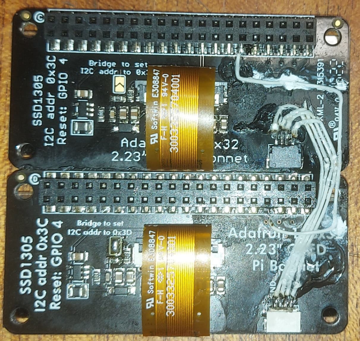
    • Many i2c devices allow for changing the programmed i2c address via switches, jumpers, or small selectable solder-bridges.
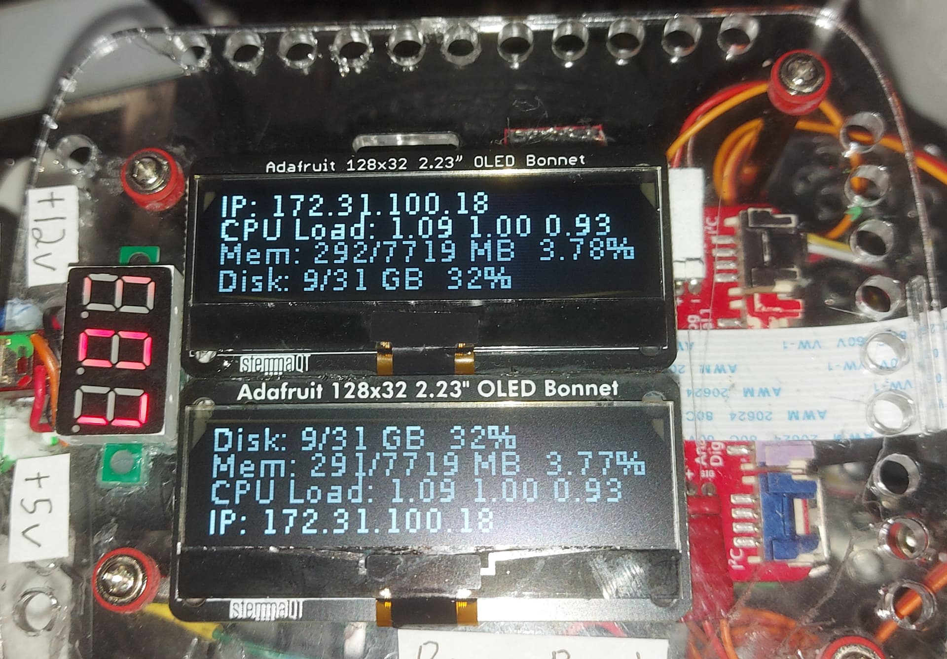
    • Unfortunately, because of the relative slowness of i2c compared to SPI, virtually all manufacturers don’t make anything larger than Adafruit’s 128x32 OLED display.

I need a display that’s at least twice the size of Adafruit’s display and was 100% i2c.

Since it doesn’t exist, (at the present time), I needed to get creative. . .

(Continued next message)

1 Like

The solution:

A McGyvver’d heap stuck together with super glue, jumper wires and fervent prayer.

I took two Adafruit 128x32 displays and glued them together, bottom to top.

. . .and I wired them together as if it were a larger display.  The fact that power, ground, and both of the i2c signals are present on the tiny StemmaQT connectors made wiring it up relatively easy - after the crazy-glue fully set!

The other wire, (top right-hand center), is a connection from an unused pin on the GPIO connector that plugs into the robot, to the hardware reset pin for the lower board.  This allows separate and independent hardware reset signals to be available for use.
 

And THAT was the easy part!
 

Next, I had to rework the software to allow full control of each device individually.

This involved a lot of digging, as the relevant data was buried deep in various snippets of the text of various places within a mountain of Adafruit articles, until I (finally!) found it.

Eventually I discovered how to make a separate display instance for each display, mutex things together, programmatically tie the hardware reset lines to their appropriate instance, program test tools, and verify that they both play nice in the sandbox together.

(Almost.  There’s somewhere where one of the displays crash which screws up the spin-lock mutex for the other display, freezing both displays solid as a rock.)

Which leads to the Musical Question:
To what extent, if at all, is the i2c buss able to recover from buss collisions between devices at different addresses?  Or does ALL i2c traffic have to negotiate ownership of the buss via a mutex?

What say ye?

1 Like

Interesting complexity but the only I2C recovery I was ever able find involved the main power switch.

Interesting. . . .

Additional research into the Dexter libraries discloses that there are two separate mutexes running, (aside from the mutexes running for other services. . .):

  1. di_mutex
  2. I2C_mutex

It appears that di_mutex is primarily used for SPI communication and I2C_mutex for i2c in eassygopigo3.

Given the following:

class EasyGoPiGo3(gopigo3.GoPiGo3):
    def __init__(self, config_file_path="/home/pi/Dexter/gpg3_config.json", use_mutex=False):
    (etc.)

if I pass “use_mutex=True” when I instantiate the easygopigo class, does it override the existing parameter in the constructor?

Is there a way to globally enable mutexes such that every instance of easygopigo and its daughters automatically inherit the use of the I2C_mutex?

===================================================

Update:
It appears that the i2c mutex is simpler than I thought.

All you need is

from I2C_mutex import Mutex

# Instantiate the mutex
mutex = Mutex(debug=False)

mutex.acquire()
mutex.release()

. . . and you’re golden - and you’re playing with the same mutex everything else on the robot is using.

===================================================

Update 2:

Things are going swimmingly for the display.

Next Steps:

  1. Verify that the rest of the robot still works properly with the display running.

  2. Generalize the status program into a generalized display routine that allows me to write to any line on either display, possibly changing fonts while writing.

Not in scope:
Creating graphical images on the display though it’s supposed to be possible.

1 Like

Very nice solution - hope all continues to go well
/K

1 Like

Actually it’s a crummy, Rube Goldberg, McGyvver’d mess.

The only things I can say for it is that “it works”, but I have to talk to the individual displays separately.

It’s especially difficult to find a font that will display reasonably well while being small enough to allow a reasonable amount of information on the screen. A monolithic screen would allow much better flexibility. But since that’s not available, I’m stuck with this.