oh my goodness  I have so much to learn… But very nice overview to be honest… Could be a nice paragraph for my thesis if I can transform this. I have to be honest… I have no idea what a json even is
  So this is basically an overview of all hardware and all functions that are called and used?
3 Likes
quick question… I just had diner and was thinking about the curved lane detection problem and had an idea. I am wondering what you think about it.
- Let’s say the image is 480 pixels high and my ROI is 360 pixels.
- I perform canny filter and blur it with a gaussian filter like I did in my picture above
- I am grouping like 10 rows of pixels together which makes 36 groups of rows
- Then I am comparing rows to get the gradient. For example group 1 with group 5 and 10. This way I should be able to determine where the lane is going roughly.
- After that I am intersecting points for each group(left lane and right lane) to transform the curved turn into a series of straight lines instead
I am not really sure if this theory is understandable . But in my head it sounded like a good solution
3 Likes
That’s one of the clever tricks graphics software does since drawing curves is very complicated and drawing straight lines is very easy, they just turn a curve into a zillion tiny straight lines.

3 Likes
I just found this github. I will look into it tomorrow. Interesting is that he is just using opencv and no machine learning. Looks promising!
3 Likes
could be a study, for optimal bin size and number of bins
2 Likes
I just thought of a lane-following idea that is stupid, simple, and requires almost zero logic. So simple, even a total neo like me can do it - in Bloxter!
Required materials:
- Robot
- GPGOS
- Line following sensor, (black version, it has more sensors)
- Bumper
I describe adding a bumper to Charlie in this post:
Grove button - object detection/bump sensor - how? - #3 by jimrh - Distance sensor.
- Road with clearly marked margins, either black on white, or white on black.
Note that it doesn’t matter if the road is curved or straight.
Logic:
- Robot goes straight ahead and continues until a line-follower sensor on the outer edge (either side), starts to flip. You can wait until two flip just to be sure if you want.
- Turn away from the side that flipped.
- Go back to step 1.
Object detection:
- If “object” is closer than “x” distance on distance sensor, stop.
- Elseif bumper switch is activated, stop.
- Else continue
Quick and dirty.
Doable in Bloxter. No fancy configuration or high-powered programming required.
Maybe I should do something like this, except I don’t have the floor space, or a wife willing for me to make a big road in the middle of her imported silk tapestry rug.
Of course you probably can’t do something like this for actual credit, but you could do something with a line follower and a bumper to detect edges and obstacles you can’t see/detect.
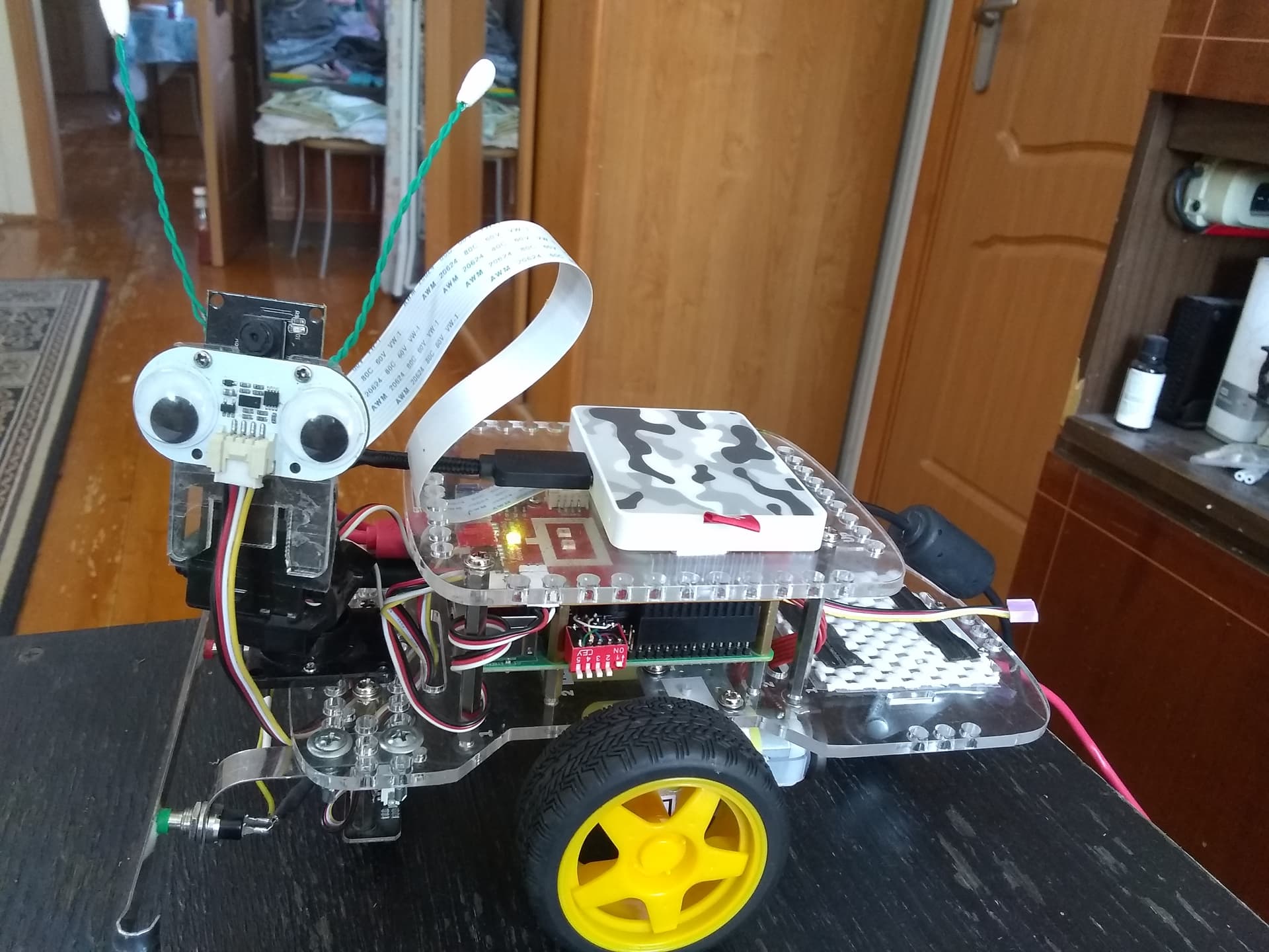
Here’s a picture of Charlie showing his bumper, SSD, and the dip-switch that I use to select which operating system I want to boot. (My multi-boot project is an entire thread in itself!)
3 Likes
Congrats. I’ve been lurking since I have nothing substantive to add. But agree completely with @cyclicalobsessive and @jimrh - get the minimum expected done. If you have time after that you can add additional bells and whistles.
Looks like you’re a long way to an MVP (minimal viable product). Great work!!!
/K
2 Likes
Perhaps this is over thinking it?
If you gave me the
- mid point of the bottom of the image p0,
- the midpoint p1 between the left lane line pBL and right lane pBR at the bottom of the frame,
- the mid point p2 between the left lane pTL and right lane pTR somewhere between 1/3rd to 1/2 of the vertical field of view (FOV),
I expect
- the radius of lane curvature is related to dH(p2:p1) for rotation amount/heading algorithm
- the current heading error from the lane at the vehicle is related to dH(p1:p0),
- the current position in the lane is (p1:pBLpBR) for lane keeping algorithm
- if one of either pBL, or pBR are not found, use half the previous lane width (in pixels) at the bottom to compute p1
- if one of either pTL, or pTR are not found, use half the previous lane width (in pixels) at the forward point to compute p2
and all those other lines you are computing may only be good for proving to a human you can process an image for human consumption. They may be of redundant value or even a drag on a basic control algorithm. Later with more processing resource, perhaps more points improve confidence or allow for broken middle lane lines, or the missing lane lines when passing an exit.
For initial proof of concept, without a GPU to do all the calculations, and running an interpreted/bytecode language such as Python - start simple and optimize later.
As another investigation, running a Kalman Estimation Filter on p1, and p2 each detection loop, might cover the temporary loss of both lane lines condition.
3 Likes
Can you elaborate what you mean with dH? 
3 Likes
I have two generell questions about a raspberry pi that I just can’t figure out.
- I am using VNC to work with the pi. The resolution of this pi is set at 640x480 or 800x600 not sure right now. But I couldn’t find a way to increase it. If I open the command or showing camera footage the whole screen is used. Do you know a way to increase the resolution up to a reasonable amount?
- Since I am coding on VS Code on my computer, I am copying codes that I tested to the pi with the remote ssh extension. But if I want to test images or videos on the pi I need to send them from my computer. I figured out that VNC has a function that allows me to send data from the computer to the pi. But not the otherway around. So If I save images from the raspi cam on the pi and I want to use it on the computer first to test it. I need to screenshot it. Is there a better way to do that?
3 Likes
First:
To change the resolution:
- Use a keyboard, monitor, and mouse to connect to the robot.
- In a terminal window, type
sudo raspi-config - Select “display options” and then “display resolution” (at the top).
- Select a reasonable resolution.
(I am not near my system and I am doing this from memory. Names may be slightly different.)
Reboot and see what you get. Retry as needed to get it right.
I noticed that to get a reasonable resolution, I had to set up a desktop, and set that resolution to something reasonable. Since VNC simply “mirrors” the desktop, you need a configured desktop to mirror.
Second:
What kind of a computer are you using?
On a PC you can use FileZilla to set up a secure connection to the 'bot to transfer files.
Another thing you can do with VS Code is to set up remote development. that puts some software on the 'bot and allows you to run VS Code on your main system and develop code directly on the 'bot itself.
You will have to look that up yourself as I am not near my system right now.
2 Likes
So the one method to change the resolution is with peripherals and a monitor? But that also means that I need to have the monitor connected at all times if I want the resolution to not change back, right?
I am using a win10 pc. Nothing special. Okay FileZilla ist good to know. I am already using VS Code with the remote ssh extension to code on my pc and run the code on the gopigo
3 Likes
No. You don’t need the monitor all the time, just to configure the desktop resolution.
You can use VNC all other times.
As far as huge picture resolution is concerned, you might need to look at wherever the camera/video is configured to set that differently.
2 Likes
You do not need to attach a monitor/keyboard, just ssh in, and make changes:
2 Likes
Use scp secure copy command but FileZilla is easier
2 Likes
dH Delta horizontal = x1 - x2 (pixel)
dV Delta vertical = y1 - y2
2 Likes
Oh my god… It worked… Thank you so much!
3 Likes
Nice, Filezilla also works Thanks you both!
3 Likes
Since I cannot see what you are doing, I’m not sure what resolution you’re talking about.
If everything else is OK and its the CAMERA or VIDEO that’s taking too much room, you can change that by adjusting the /etc/uv4l/uv4l-raspicam.conf file.
Somewhere between lines 50 and 60, (depending on the version of raspicam and the config file you are using), you will see something that looks like the following:
(this is from the current version of raspicam’s uv4l-raspicam.conf file)
encoding = mjpeg
#  width = 640
#  height = 480
framerate = 30
#custom-sensor-config = 2
With the width and height lines commented out, the video image is HUGE - filling the entire screen/browser width.
Un-commenting these lines makes the image smaller, but still too big for what I want.
The original version of the config file as shipped with GoPiGo O/S 3.0.1 has this:
encoding = mjpeg
width = 320
height = 240
framerate = 15
#custom-sensor-config = 2
Which produces an image that’s a bit too small for my taste, and a bit blurry, so I increased the size by half, and upped my framerate to 30.
Viz.: (my current settings)
encoding = mjpeg
width = 480
height = 360
framerate = 30
#custom-sensor-config = 2
. . . and that produces an image that is large enough, but not TOO big.
Maybe this will help?
Follow-up note:
In order to maximize the field of view, make sure the settings maintain a 4:3 aspect ratio.
2 Likes