The actual tests and what they mean:
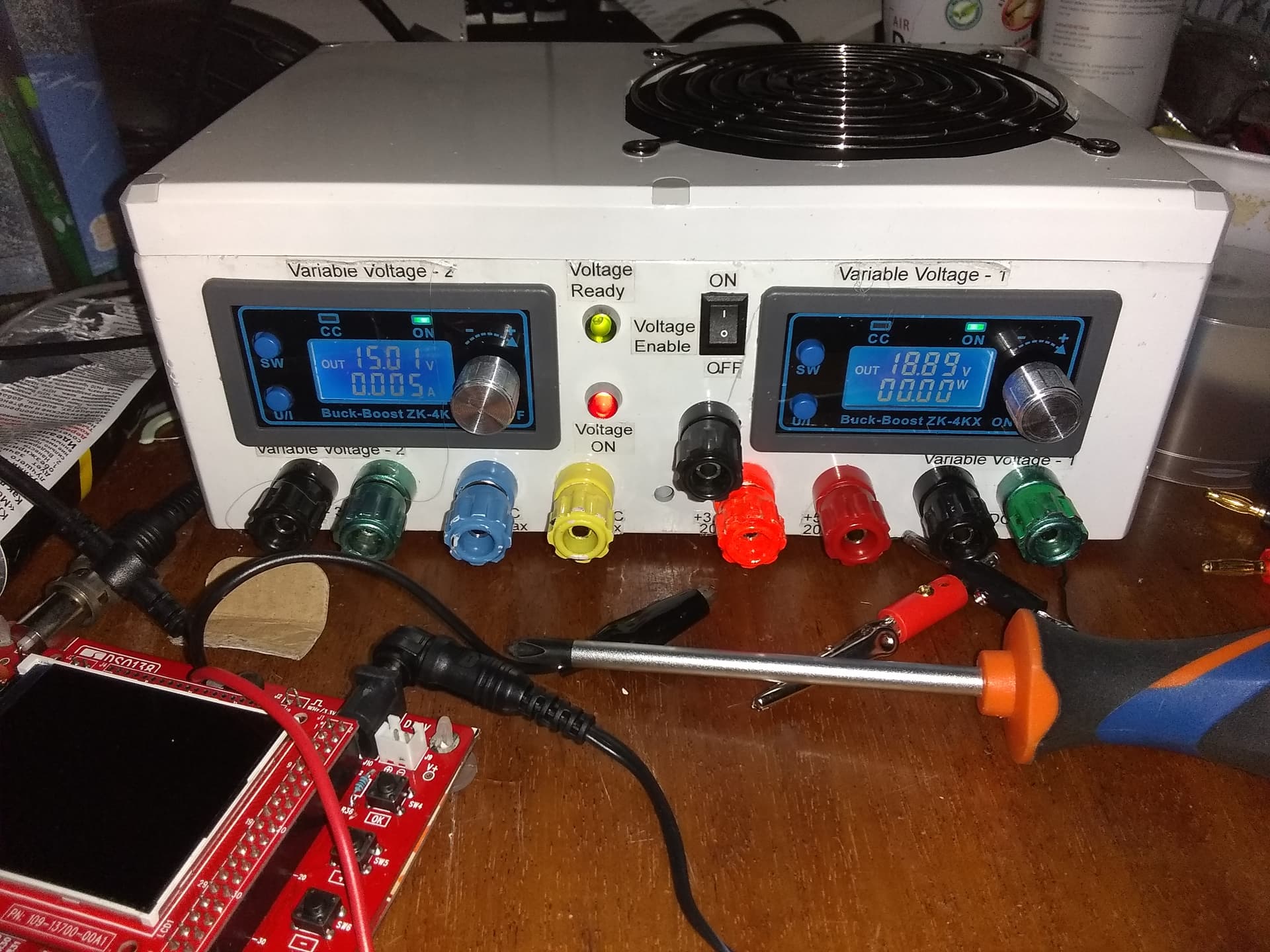
For the Bench Supply, I have a set of banana plugs terminating in alligator clips.
For the ATX supply, I stuck a wire into a connector’s ground pin and attached the 'scope to the +5 and +12 pins next to it.
The ATX supply:
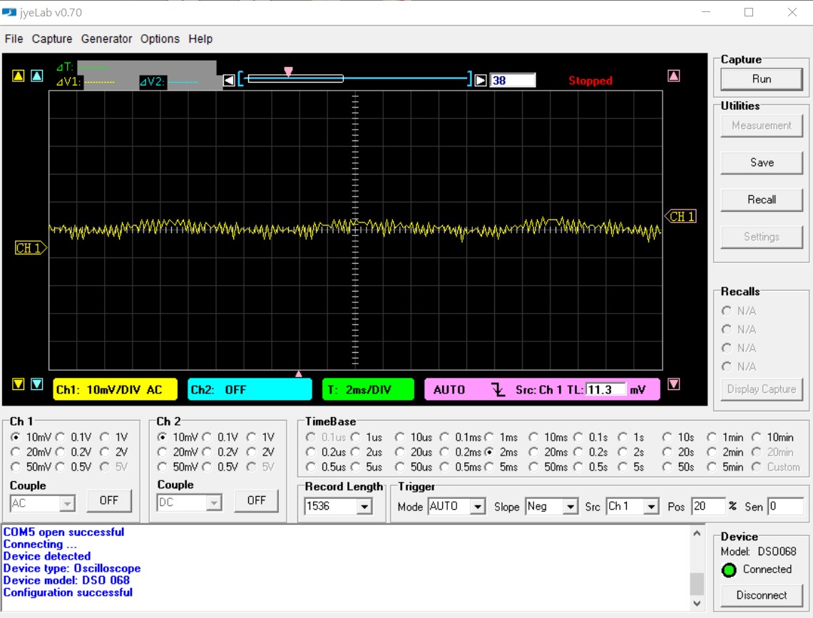
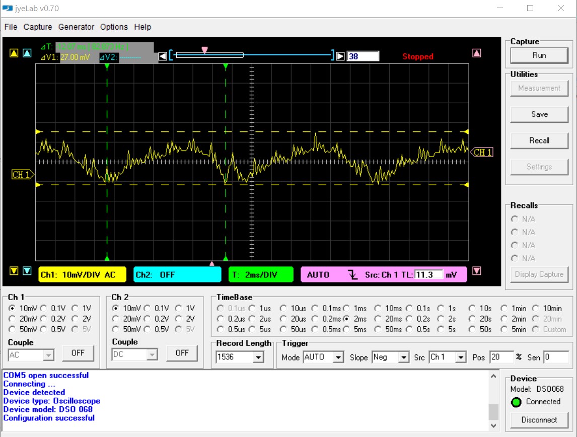
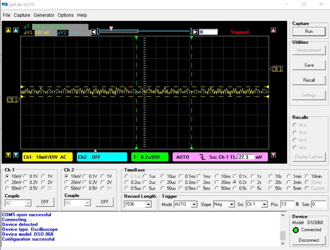
+5v
Note at the lower left corner of the “oscilloscope” display, each vertical box represents 10mv, (0.010 volt) of signal.
If you look closely, you can see digital noise that consists of (approximately)
- 3khz switching noise. . .
- That is grouped in bursts with a period of about 300hz
- With about a 80hz overall ripple
- The total noise amplitude is about 10mv.
This periodic noise is not unusual for a switching supply.
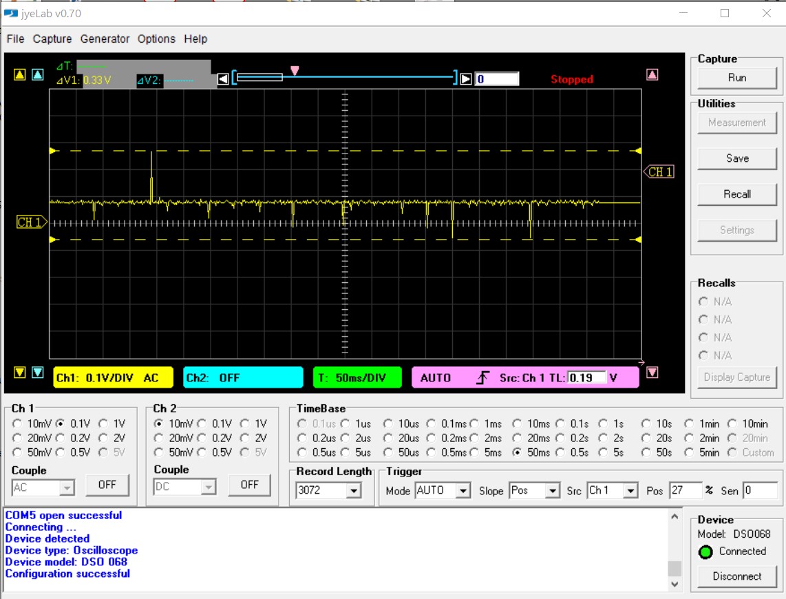
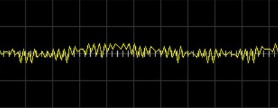
By comparison, here is the +5v from the Bench Supply:
It doesn’t look like much to begin with, but look at the ranges!
This view shows a totally aperiodic (random) noise of 330mv! (0.3 volts)
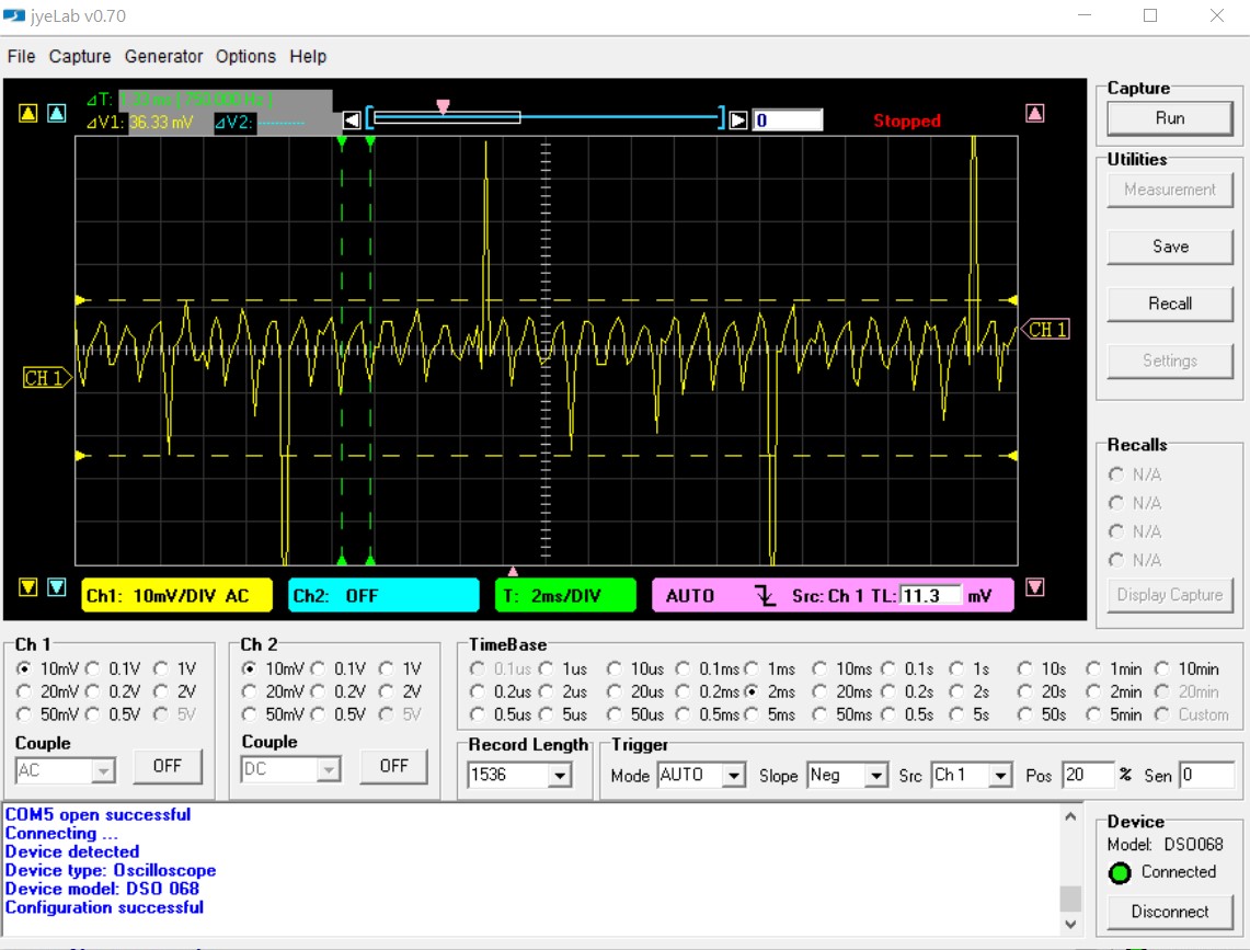
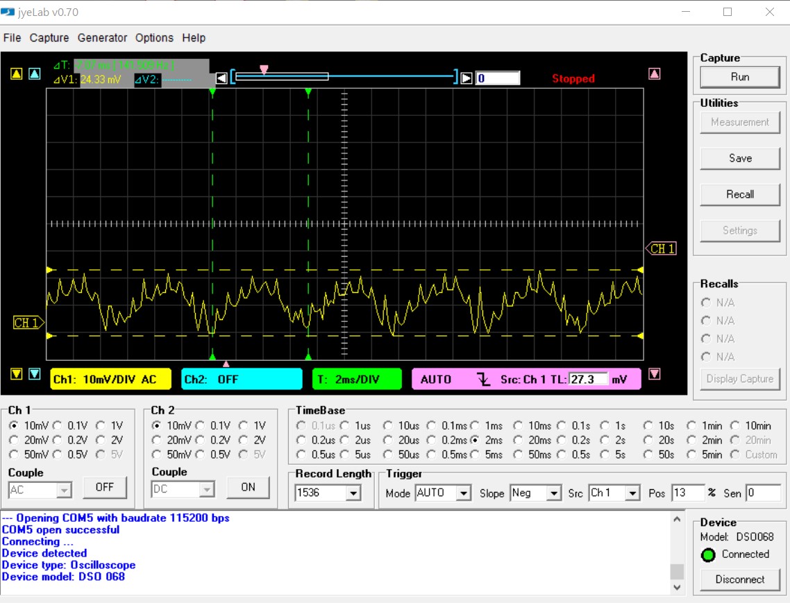
Zooming in we see. . . .
Here you see:
- High-intensity pulses with a total period of about 43hz.
- Over 36 mv of high frequency ripple. . .
- With a ripple frequency of about 750hz. . . .
- With glitchy spikes all over the place!
Remember the high frequency ripple on the ATX supply was about 3khz. Here, it’s less than 1khz. And that’s slooow for a switching supply like this one.
Now, let’s look at the +12 supplies:
First, the ATX supply:
Here you see:
- The same approximately 3khz switching noise. . .
- And the same appx. 300hz bursts. . .
- And the same 80+hz ripple. . .
- With an overall 27mv PP ripple. 27mv out of 12 volts isn’t too nasty, 'eh?
Since the supply generates the +12v, which is then filtered and regulated down to +5v, the increased ripple on the +12v line isn’t surprising.
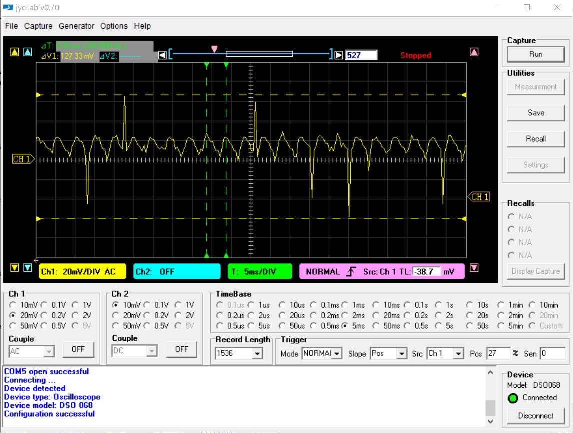
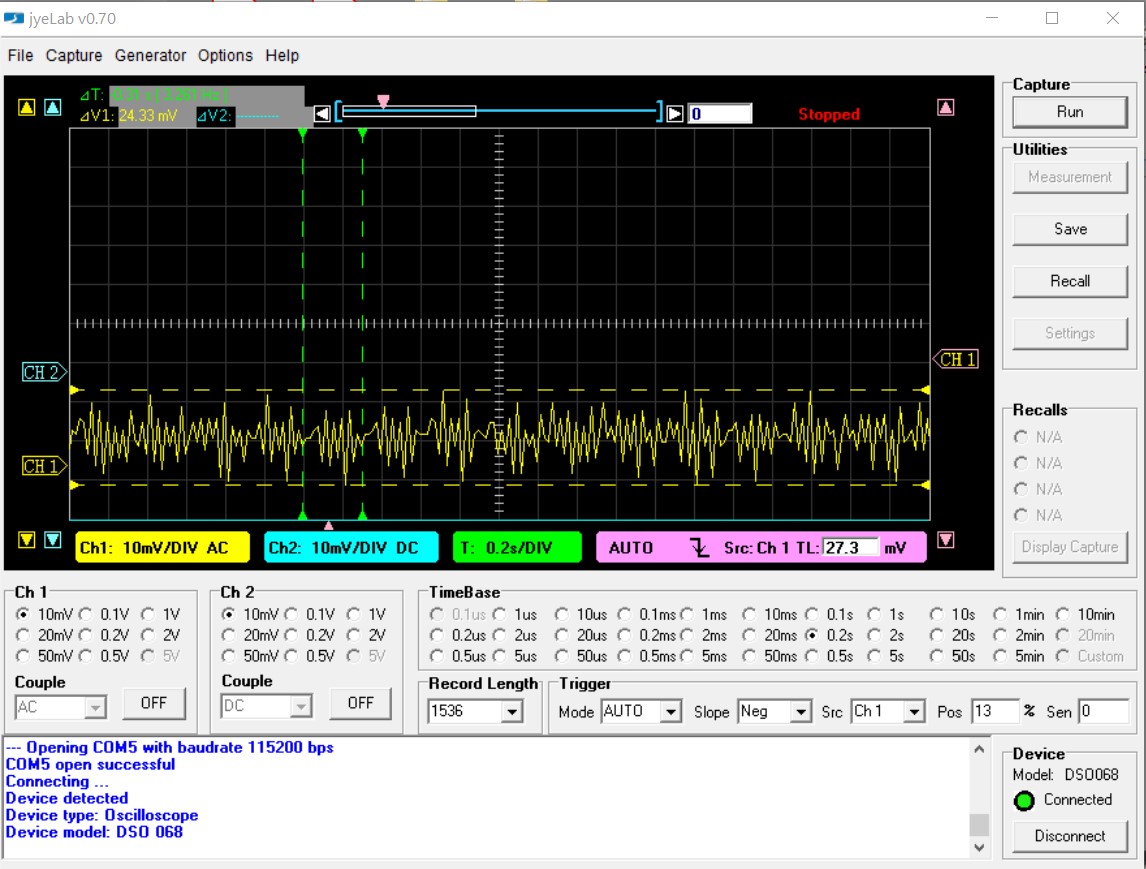
Now let’s look at the bench supply:
Here we see:
- 200hz of regulator noise.
- Random spikes giving almost 130mv of peak-to-peak noise.
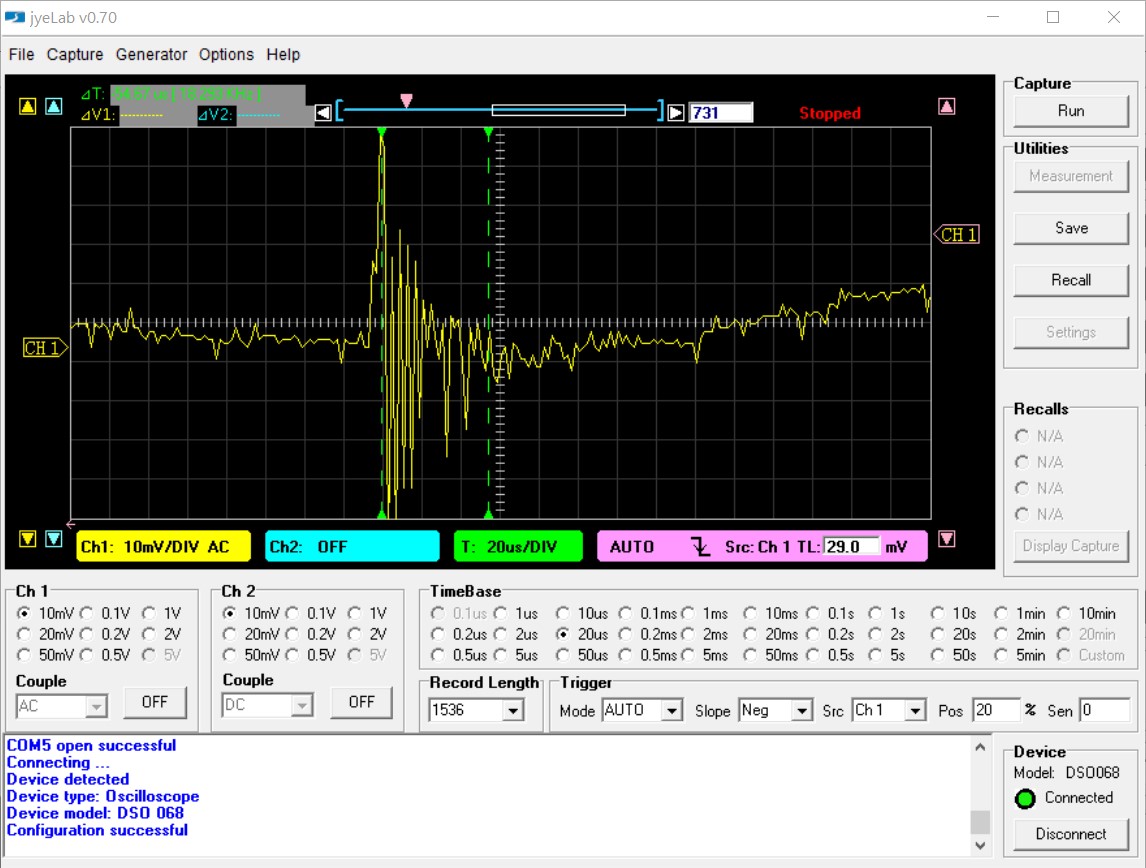
Wandering through the waveform, I found THIS monstrosity!
- A high-frequency burst that was almost 55μs long
- Ringing at almost exactly 250khz. . .
- With an amplitude that was off-the-scale for the 10mv/div range
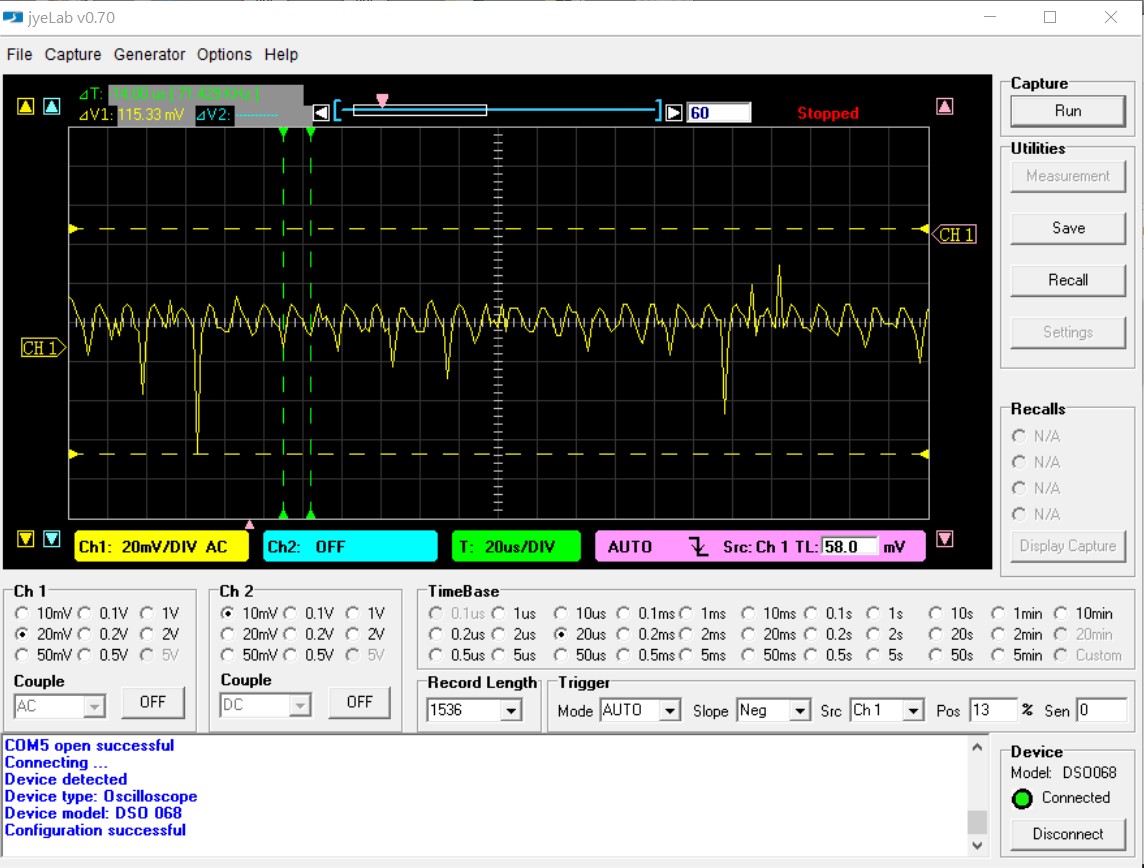
Restarting the supply showed a different waveform for the +12 supply.
(. . . and exactly
HOW did that happen?)
It’s essentially the same as the first image, except that the regulator ripple is now almost 71.5khz instead of the 200hz it was before! My guess is that the regulator control chip is toast, or something related to it, and the regulator ripple frequency depends on the time of day, phases of the moon, the color of my shirt, or whatever. Whatever - that’s NOT a good thing!
Either that or I zoomed in and found a “subcarrier” ripple on the main regulator ripple, I’m not exactly sure. Maybe it’s sending clandestine encoded messages to the KGB?
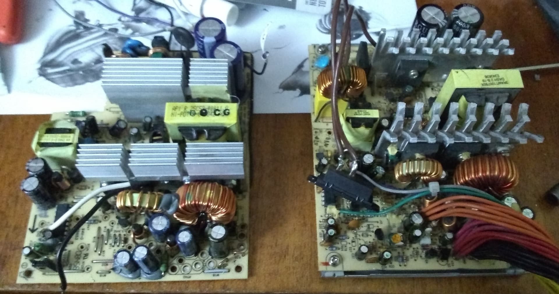
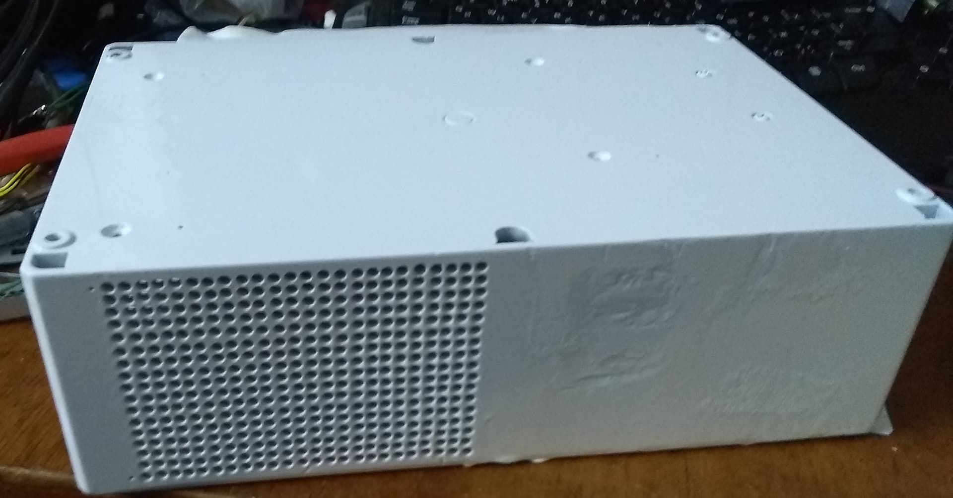
In any event, I think I’ve established enough “probable cause” to remove this power supply board and replace it with the ATX supply’s board.
My next step is to remove the ATX supply’s PCB from its case, without removing the connectors, and then re-test on the bench in vitro as it were to see if the absence of the case and/or cable routing changes things.
=============================================================
The real pressing question if you have any engineering/management skills is “What happened?”, and “Why didn’t I realize the first PCB was toast before I installed it?”
Well, (as I said before), we all know hindsight is 20/20.
Even more so is the fact that, since I started this journey, I have had the equivalent of a college-level class in switching power supply design and use, and things that I saw - and ignored - before are now known as gigantic flashing red beacons saying “Run Away!!”
-
The original instability of the +5 standby voltage and the two over-voltage-damaged electrolytic capacitors I changed.
-
I now understand that the main power-supply controller and regulator IC is the part that generates the +5 standby voltage. It is also responsible for the health of all the other signals and voltages on the board.
-
There is no “good” reason for those two electrolytic capacitors to have been bubbled-up like they were.
-
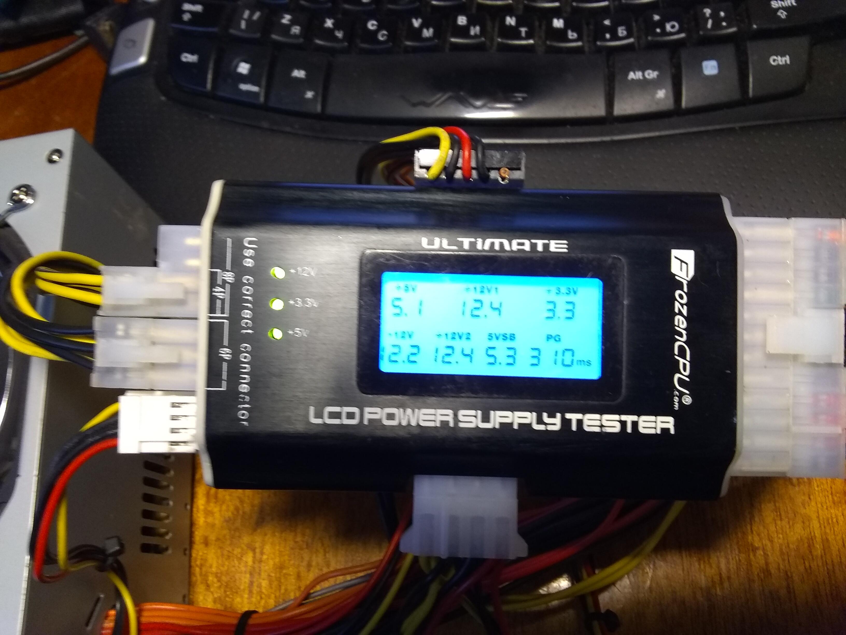
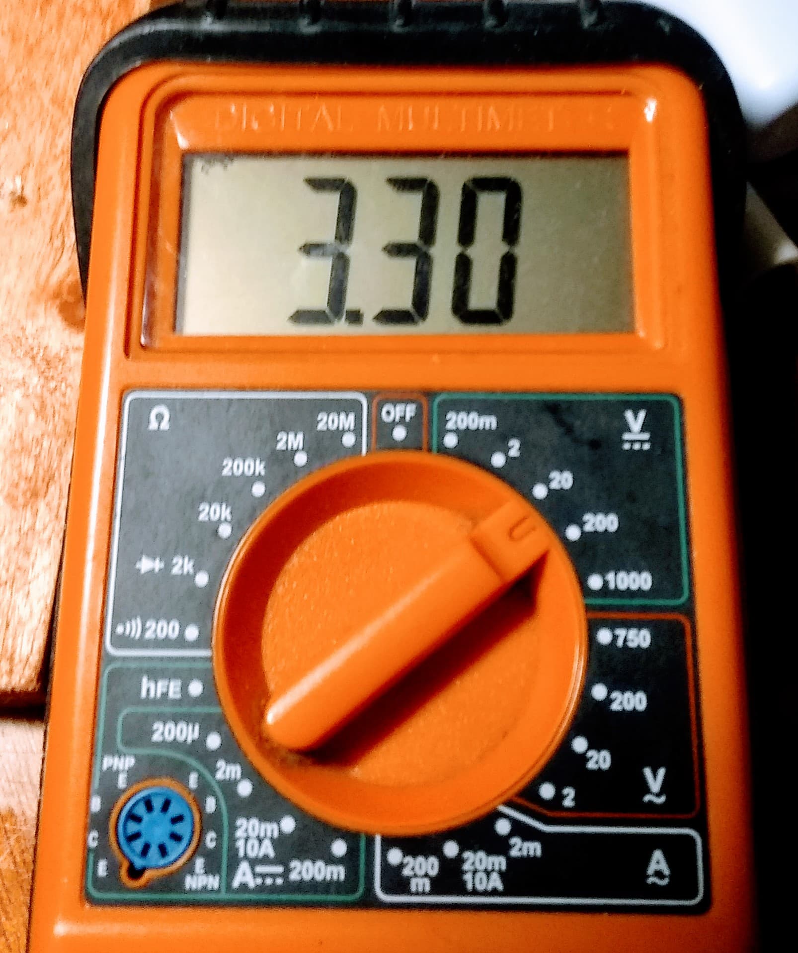
The original supply, prior to being disassembled, had a “Power Good” assertion time of something like 750 to 800ms. It should be less than 400 or 500ms.
Viz.:
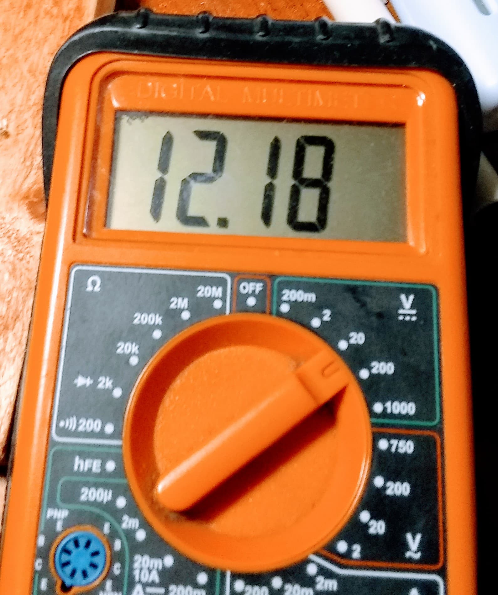
Notice that the readings from the ATX supply are right on 300±ms which is what I would normally expect - and I now realize that any significant deviation is a ticking time-bomb.
-
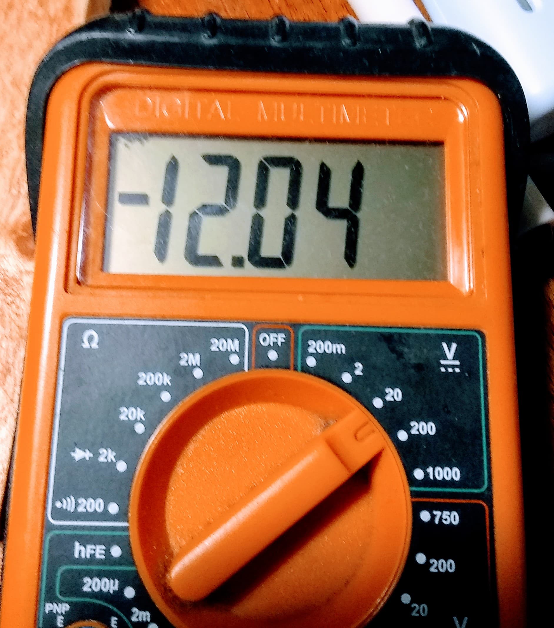
Other supplies, like -12v, also varied when originally measured on this same meter as I am using on the ATX supply now, but I did not realize the significance of what appeared to be a minor variation in voltage. I now realize that ANY variation is suspect.
In total, (and not unlike the ROS adventures of my dear and esteemed colleagues), this has been, (shall we say), “educational”. I’ve seen more datasheets, graphs, articles, explanations, and other stuff in the last couple of months than in the entire year prior! And that includes the TalentCell battery research I did.
In summary:
-
I feel like an absolute clod.
There are other, more accurate ways of describing this but - since I don’t know how much British slang Nicole knows, (and she IS a lady), I don’t feel comfortable using it here.
-
I have learned a LOT about the inns-and-outs of switching power supplies. For those of you who are into unique and interesting circuits, look up “joule-thief”, an interesting charge-pump type supply commonly used in outdoor solar lighting. It’s about as closes as you will come, electrically speaking, to turning a sow’s ear into a silk purse.
-
More important, I’ve learned what to look for. I now have a clearer understanding of what’s important and what’s not.
Spoiler: In a switching supply, it’s ALL important. Everything is so closely tied together that any tiny thing can, and will, affect everything else.
-
As an old boss used to say, “The Devil’s in the Details.”
-
And I probably should have gone out and just bought a supply instead of trying to “grow my own”. 
What say ye?