TalentCell YS1203000 "State of charge" monitor

One of the reasons it is especially important in power conversion circuits, (and the final stages of an audio amplifier are simply a special kind of power conversion circuit), is that the circuit often handles significant current with respect to the output signal.

A large positive current pulse has a correspondingly large negative current pulse.

In the case of a DC supply, the “signal” is the absence of a signal.

Additionally, circuits often are extremely sensitive to voltage supply noise. Though a circuit may have trivial gain, (or in the case of a digital circuit, unity gain), the gain between the power rails and the output can be tens of thousands. Miniscule ripple can turn into a significant part of the output.

There are entire college classes on managing power supply noise and it’s not a simple topic.

2 Likes

That “wire” may be the shunt for the current feedback loop. Other circuits use a fractional ohm resistor as the current shunt.

In any event, that “negligible” resistance may not be negligible after all. :wink:

2 Likes

SUCCESS!

This is the supply during test and calibration.

Note the +5 reading. The +12 is just like it.

This is the fully assembled unit. The top screws are not in, and I haven’t added feet, but that’s piddle.

You can see both the “voltage ready” and “voltage ON” LED’s lit

Here is a view with the cover off.

I checked the vents in the back, and there’s lots of air flow, so I don’t think overheating will be a problem.

The next steps are to calibrate the two front panel voltage meters by adjusting to a known precision voltage output, and then adjusting the reading to match.

That, cover screws, and feet are all that remains.

I’m going to away for the next couple of weeks, but when I get back, (and clean up the mess!), I will continue the battery tests.

2 Likes

Looks great.

Hope you enjoy your trip.
/K

1 Like

One robot guy I follow on Twitter just paid over $500 for similar spec “Only Dual” supply.

Great Job!

2 Likes

Here’s an example of just that case:

A piece of #14 solid copper wire is the 10 amp shunt resistor on my multimeter.

It’s the solid wire in the lower right hand corner.  If you look really closely at the left side of the wire, you can see where they notched it with wire cutters to calibrate the resistance of the wire.

It will read as a dead-short on anything but a milli-ohmmeter.

1 Like

I learned another thing - didn’t know you could do that.

Cool - thanks
/K

2 Likes

Another thing I learned is that the 10A current range on my backup multimeter needs recalibration. The indicated current was about 0.3A different than the calculated value based on measured resistance and applied voltage.

Either that or the voltage/resistance ranges are off.

I’ll check that when I get new batteries for the main meter.

2 Likes

First milestone with the new power supply met:

Characterize voltage curve for the GoPiGo:

2 Likes

Major disaster.

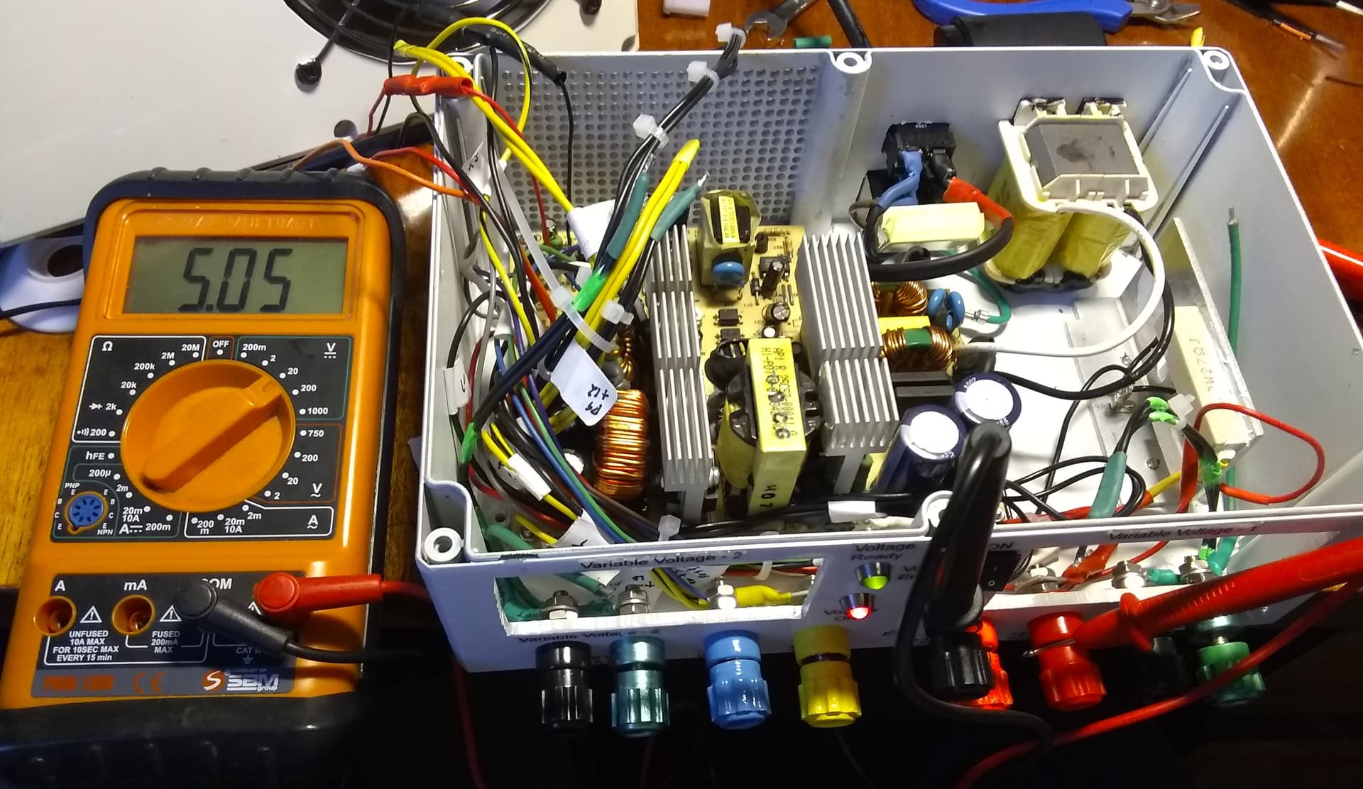
While trying to calibrate the various voltages and currents on the supply, I ran into the problem of, (seemingly), significantly different values between more than one of my multimeters, as well as calculated values compared to actual values.

After trying a number of different things, I (finally) had the brain-storm of putting the 'scope I bought on the outputs.

Major, make that read MAJOR, amounts of power supply noise on all the outputs to the tune of fractions of a volt!

200+ millivolts, (> 0.2 volts), of noise peak-to-peak is GARBAGE!

Bzzzzzt!

We’re sorry but your answer MUST be in the form of a question.  (But thanks for playing!)

Conclusion:

The fancy Cooler Master ATX power supply I was basing this entire project on is, in a word, trash.  Or, spare parts.

I found another ATX supply with a, (ahem!), great high-end brand name, (Power Man!!), that I dropped onto my ATX supply tester, (to start it and give it a load), and I placed the 'scope across the +12, +5, +3.3 (etc) voltages and the noise was in the microvolt range - thousandths of a volt.

You may ask why didn’t I do that with the previous supply prior to entirely building it out?

Aside from “hindsight is always 20/20”, I didn’t have the 'scope available to test with as my original kit-scope spontaneously self-destructed a couple of weeks after I bought it, (a known defect for a certain production series of the DSO138 based on a defective chip - and I just happened to get one of those old ones), and I had to wait for the replacement kit to arrive.

Result:

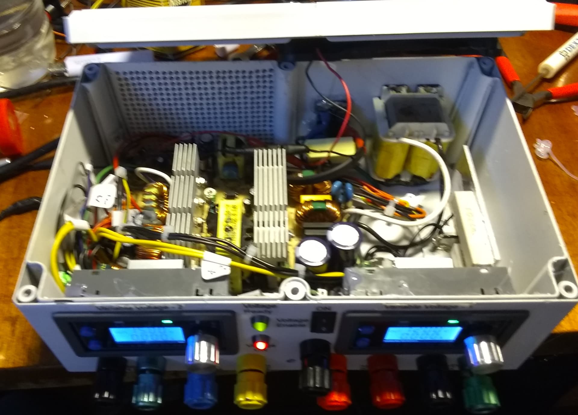
  1. I now have to completely disassemble and rebuild with a different power supply PCB.

  2. The PCB is sufficiently different so I will have to re-drill, move things around, and rebuild.

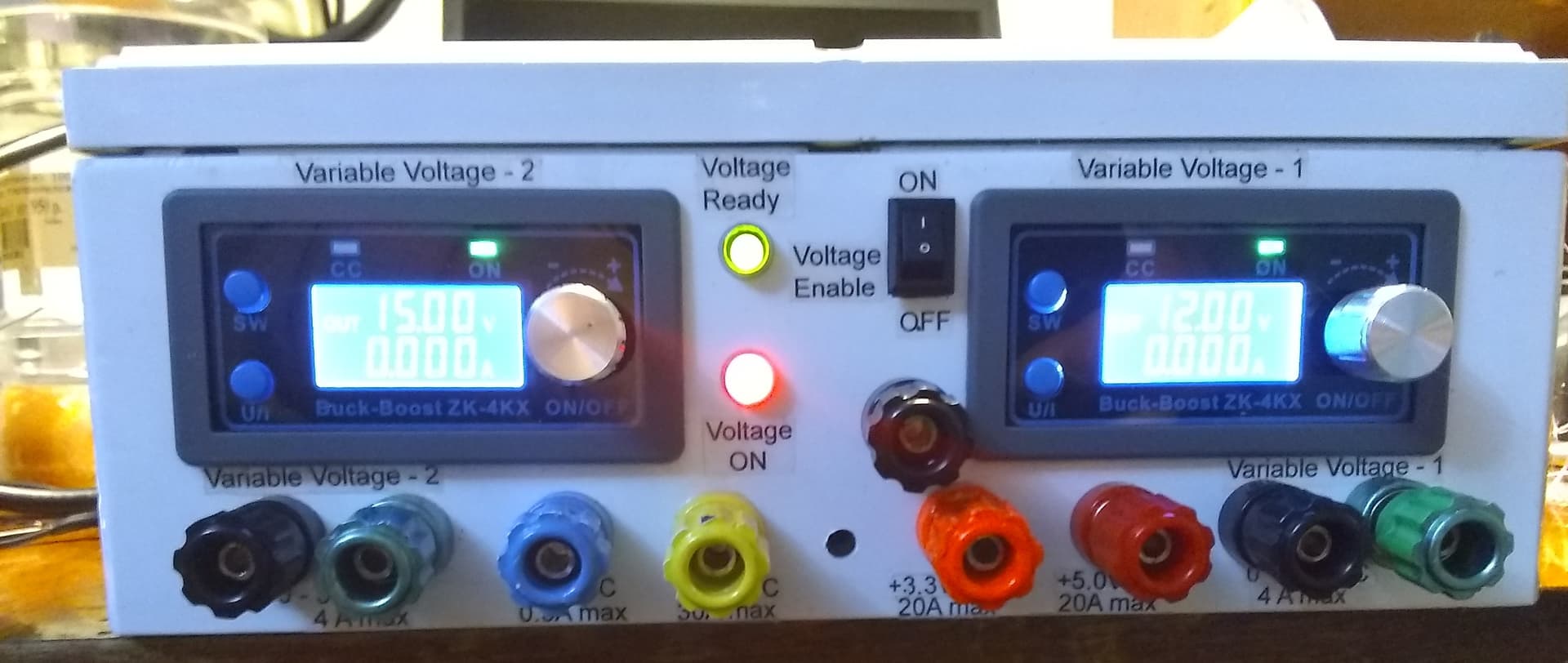
  3. This supply is a dual-voltage supply, capable of using either 110v or 220v mains power, which is a good thing.  However!  That also means that I have to change the rear-panel layout to accommodate the voltage selector slide-switch.

It’s like Chutes and Ladders where one of the spots on the game board, just prior to winning, is a “chute” that takes you back to the beginning and you have to start all over again.

Errrr!

2 Likes

You’re like Mark Watney in The Martian - overcoming each challenge as it comes.
/K

2 Likes

Have you removed the “bad” supply and tested it likewise?

1 Like

I feel like the guy who was stranded on Mars and has the great idea of building a greenhouse and burning hydrogen to provide both heat and moisture.

Until the storm hit and all he had left was “flash-frozen leafy greens”.

Is that the movie you’re talking about? I saw a part of it at The Museum of Science in Boston, back when I was allowed to travel.  The poor sod is stranded there on Mars, up to his eyeballs in poop, and the only thing he had plenty of was bad luck.

Luckily I have another supply to work with.

Unfortunately, my wife is getting tired of the mess in the living room.

I have a couple of things I want to try before ripping everything apart, to verify that when I’m done that I won’t have another noisy monster.

I am really considering surgically forking this thread to create a “talantcell” thread and a “power supply” thread by migrating messages.

As it is, this has seriously diluted the original thread’s topic.

Ideas on how to untangle this mess?

Maybe I should just end it here with a -30- and create two new threads going forward?

1 Like

No can do.  Nice idea, were it only that easy!

The ATX tester plugs into the ATX’s MoBo connectors, and those all get cut off to wire in all the switches, binding posts, meters, and such-like within the supply’s enclosure, so it can be controlled by the person using it instead of the PC’s motherboard circuitry.

The new enclosure supplies the loads that a working MoBo provides, and adds connections to the outside world.

Essentially what you do is completely disassemble the ATX supply and re-assemble it into a different enclosure with different connectors.

It’s just absolutely beastly bad luck that the “fancy, high-end supply” I was using was seriously junk.

Got my vote - anyone wanting to know the history can follow your link back

1 Like

Ok, then perhaps measure as you disconnect each output one at a time in the disassemble/extract process?

Just to be sure there is not some weird thing that is going to bite you when you put the new super wiz-bang “guaranteed good” supply in place.

1 Like

Yep - that’s the one. Worth a watch when you get the chance - Matt Damon does a great job as Mark Watney. But I like the book better - more detailed.

seems reasonable.
/K

1 Like

Sigh. . . .

If it were only that easy.

Messing with a modern switch-mode power supply is not unlike Keith and yourself working on ROS.  It all seems soooo very easy, until you discover that the (teeny-tiny little process) waaaaaay over there, (that you didn’t even notice), is what makes Dave know if he’s still in Kansas or not and the “missing yellow-brick-road” messages from state publisher “Glenda” have been driving you BONKERS!

So it is with switching supplies.

You can’t just “cut [something] out” and expect things to be peachy, as this part depends on that part getting a valid input from some other part that is dependent on this part being present.

Dizzy enough yet?

2 Likes

Fork #1.

This will contain the continuation of the TalentCell YS1204000 “State of charge” monitor discussion that was getting buried.

2 Likes

Fork #2.

This contains the continuation, (and what a continuation it is!), of the power supply project that was spawned by working on the TalantCell YS1203000 “State of charge” monitor.

2 Likes