What? Pay $500 and learn nothing, always believing you could have built it yourself and had money left over to take your wife to the best restaurant in town?
2 Likes
What’s the big deal - I probably see that much noise at Carl’s NiMH battery. Turn your scope up to 1v p-p and listen for noise with headphones.
2 Likes
Thanks - I learned a lot. And more with the description of tuning highly calibrated electronics components.
And I’m with @cyclicalobsessive - it does seem like you’ve learned a lot through this too 
/K
2 Likes
How are you getting that much noise from a battery? Or is that on his charger?
What’s important is the comparison to a known good supply and the overall stability.
1 Like
A joke, my boy. Just a joke. The pervasiveness of switching supplies with acceptable-until-you-scope-it noise is an electronic cyber-pandemic. Carl May be the last generation of robots to have a true DC power source.
2 Likes
You could always attach a class-II hitch to Dave and have him drag batteries in a tiny trailer.
2 Likes
He won’t need that until he attempts a go at the “Autonomous GoPiGo3 1k Trials”.
He’s already cabled for a second battery, but the hitch may be a little harder to do.
2 Likes
Update:
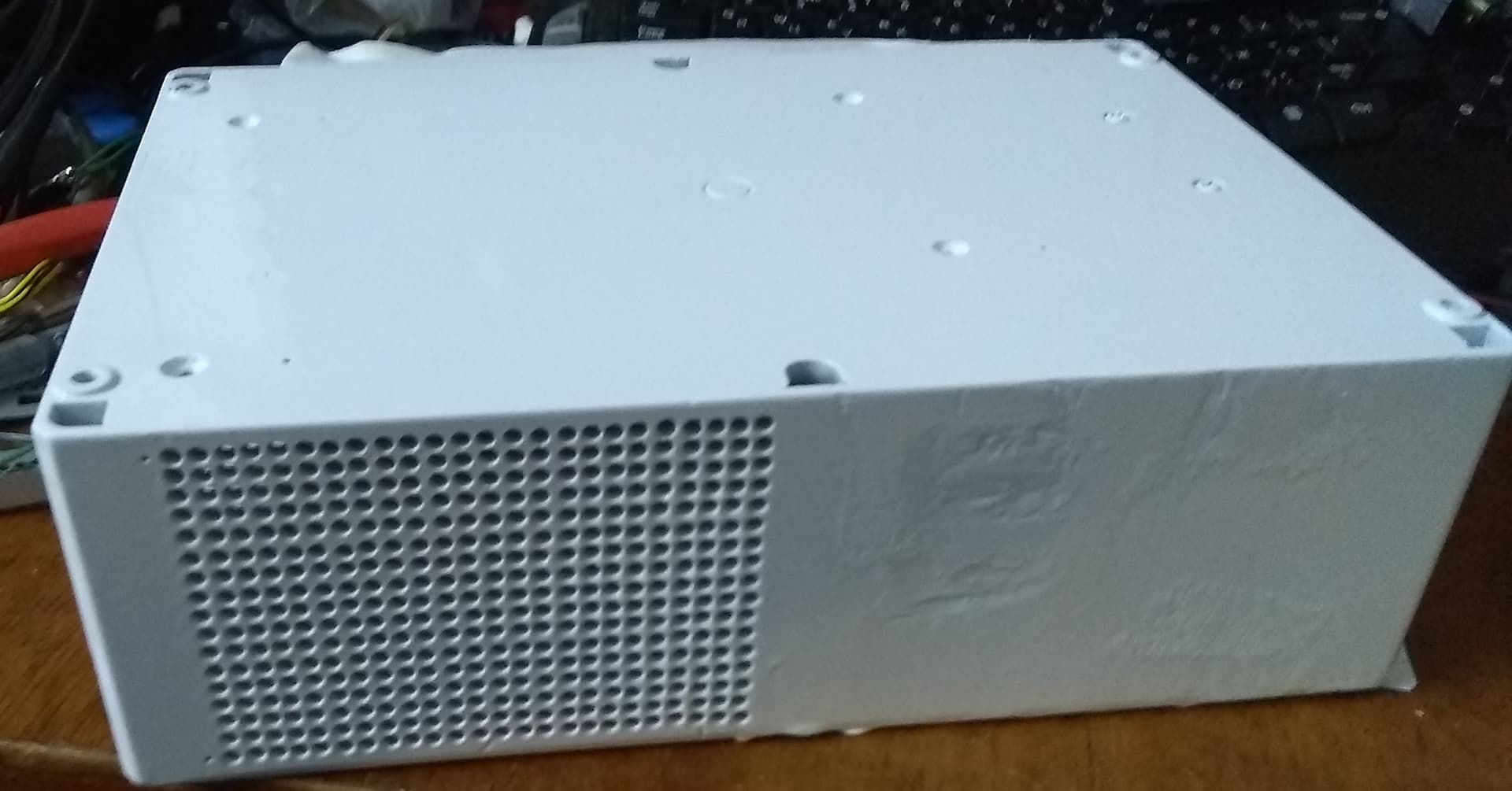
I removed the ATX supply from its metal enclosure, attached it to the tester, and tried again.
Viz:
+5v DC, 10mv at 20μs per division

+5v DC, 10mv at 0.2s per division.
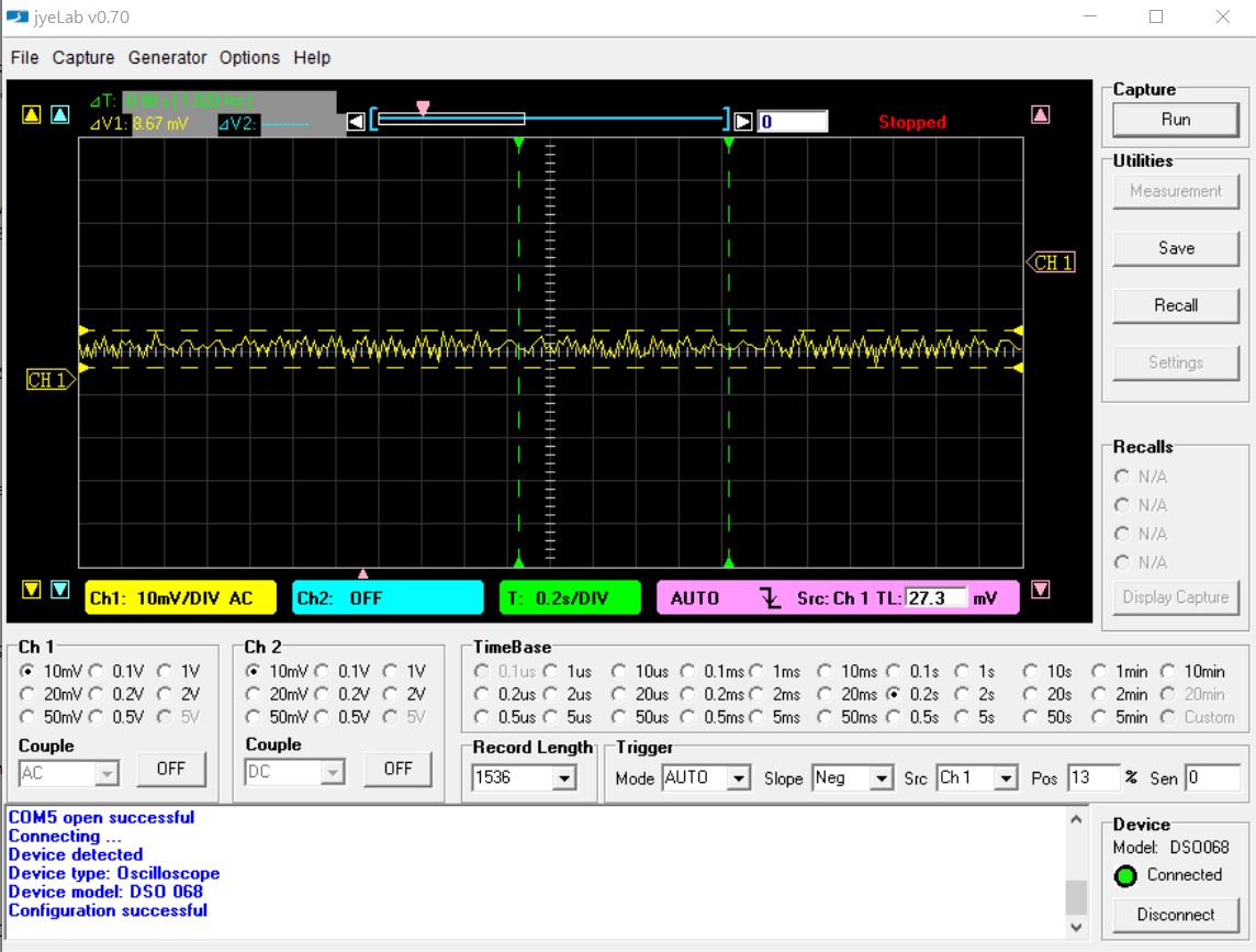
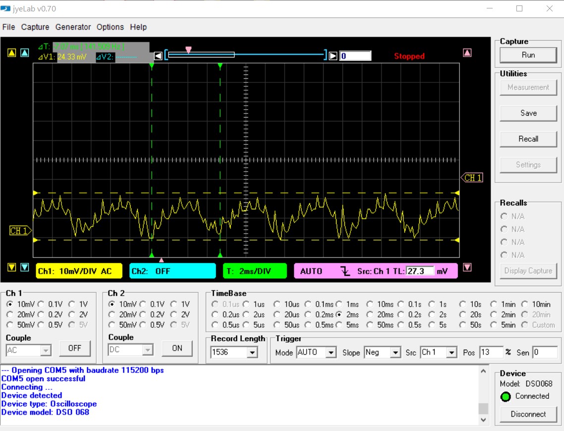
+12v DC, 10mv at 2ms per division
Note that the baseline has been moved down - that is deliberate.
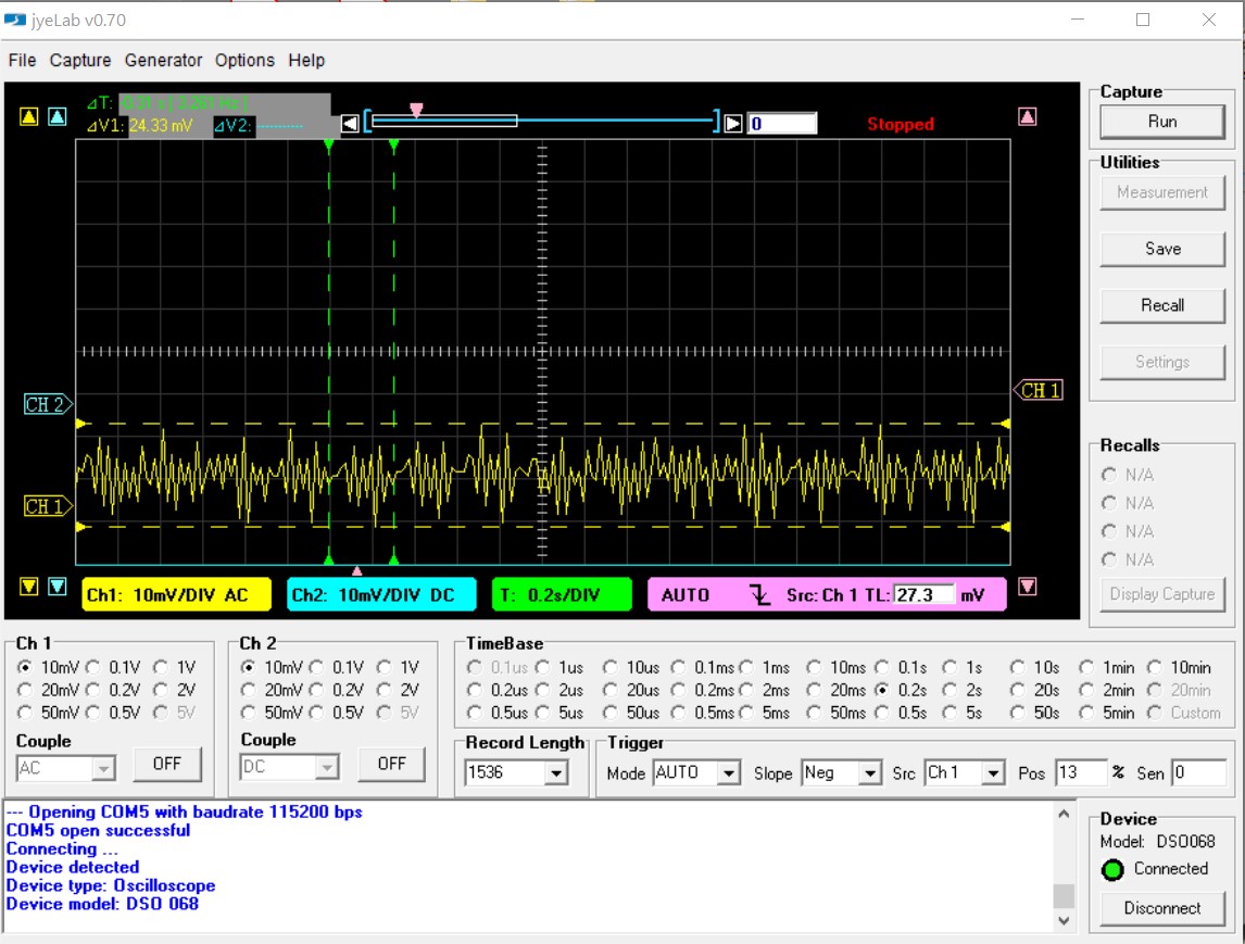
+12v DC, 10mv at 0.2s per division.
Looks good to me.
2 Likes
Update:
The new PCB is sufficiently different from the original PCB. . .
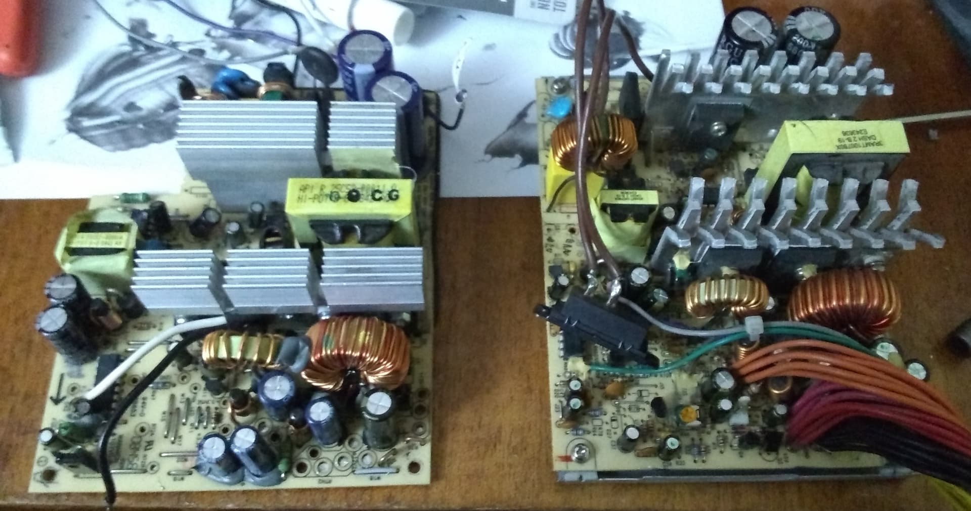
(The new PCB is the one on the right.)
. . .that I had to completely re-do and re-paint the rear of the box to accommodate the changed configuration and layouts of the connectors and switches.
The epoxy isn’t self-leveling, so it’s a bit rough looking.
Right now the box is sitting on a warm radiator to help bake in the paint.
I absolutely hate rework.
===================
On a similar topic, I am going to do as much of the assembly and fitting as possible WITHOUT removing the ATX PCB connectors. This way I can continue to test and monitor waveforms, noise, and voltage stability prior to doing all the final connections and soldering everything up.
I plan on obtaining screenshots of the measurements and comparing them with the PSU’s original waveforms and measurements prior to disassembly.
2 Likes
Its the back, so looks is not the issue - doesn’t the two different materials make cutting the new holes risking cracks and worse?
2 Likes
Stinks being me, doesn’t it?
The holes are in different places, (to the right of the original holes in that view), so it shouldn’t be too big of a problem but you gotta be careful no matter what.
2 Likes
. . . . The real problem is that it takes forever for the paint to harden to the point where I can cut the plastic. (I should have cut first and painted later, but I actually had sunny weather[1] for a day or two and I wanted to take full advantage!)
Another thing, if you notice the new PCB on the right, I decided to mount it with the bottom pan in place to provide better grounding and at least some shielding.
- The weather here reminds me of British weather. Overcast, cold, drizzly, fungus-inducing weather 99% of the time. That is, when it’s not pouring rain or snow, or blowing a hurricane.
I have a running joke with my wife that sunny weather is sufficiently rare that when the sun IS out, little kids ask: “Mommy, what’s that great big light up in the sky?!”
2 Likes
Update:
Nearly done!
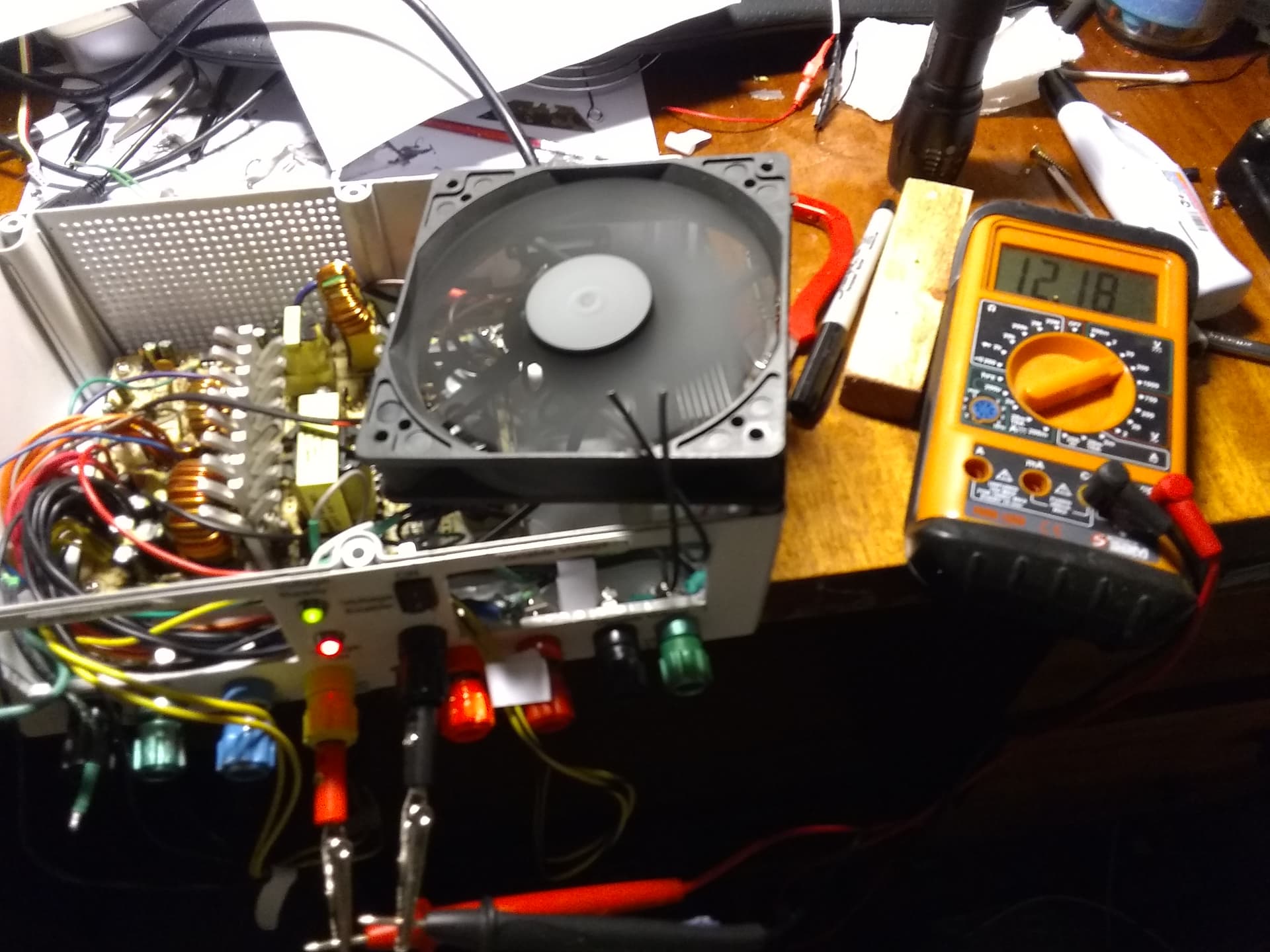
This is the initial test before making things more permanent.
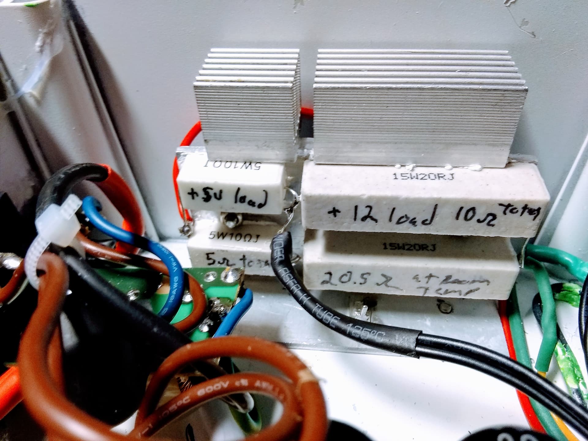
One thing I did differently is I changed the value of the load resistors - I added a second resistor in parallel, dropping the value to half its original value, increasing the steady-state load current to one amp on both the +5 and +12 voltage rails. I also beefed up the heat sink as shown below.
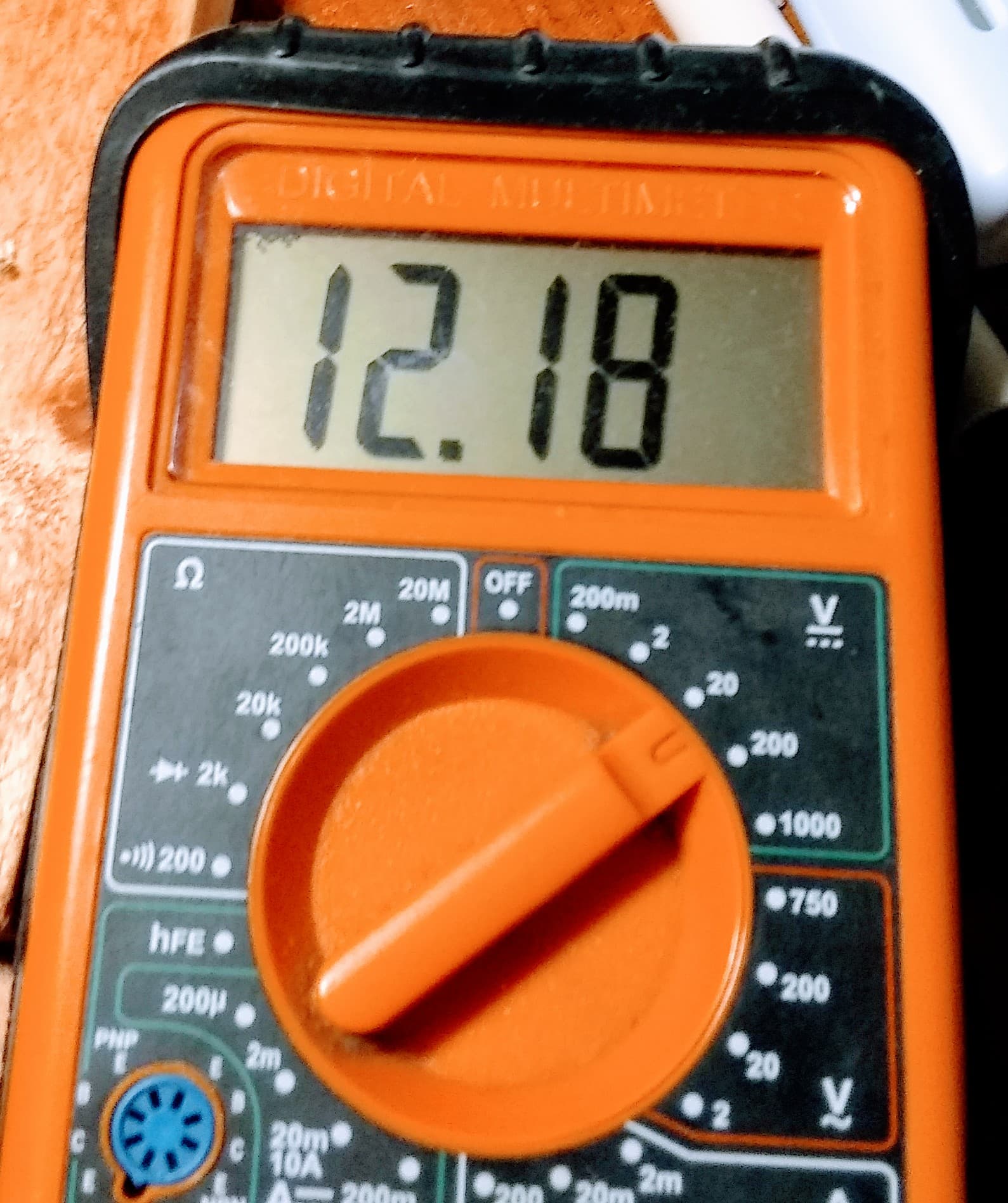
Here are the measured voltages:
+12
+5

+3.3
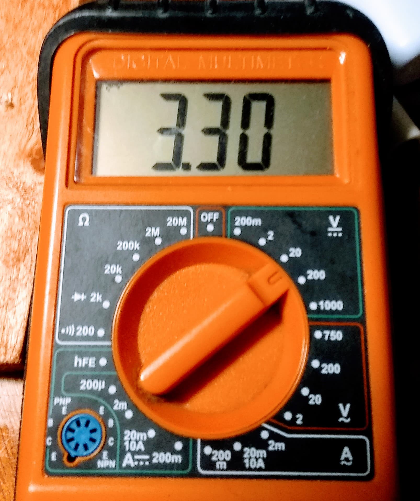
And -12
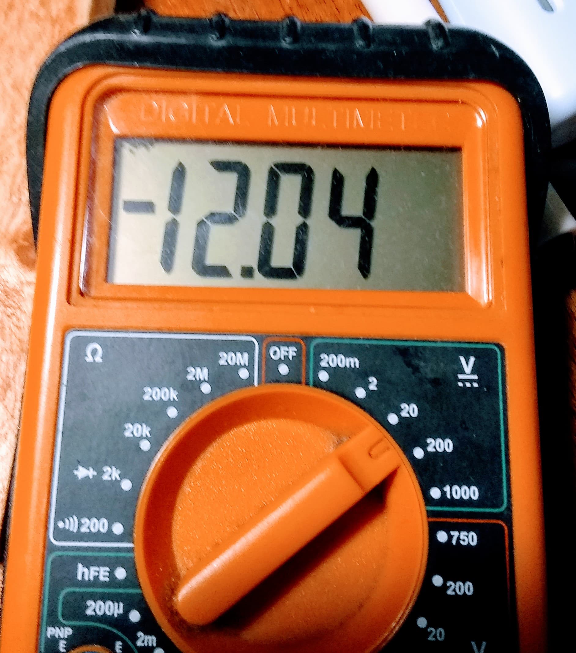
I haven’t been able to put a 'scope on it yet as things are a disorganized mess, however voltages, particularly the +12 volt output, are now rock solid.
I am expecting good things from this.
2 Likes
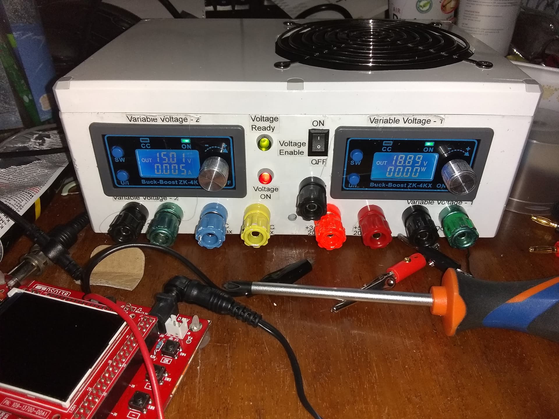
Final assembly:

This time I was able to calibrate the two front panel variable voltage power modules which was problematic the last time.
This time I have repeatability to less than 0.01 volt of variation and an accuracy, (compared with my meter) of ± 0.01 - giving me a total error of < 0.02 volts - usually within 0.01v.
The load resistors get quite hot without any cooling, but with the fan in place the heat isn’t unreasonable - where “unreasonable” is defined as “possibly melting the plastic”.
I tried to get a rough measure of the supply’s noise/ripple by placing the meter in its “AC” voltage range and measuring the AC component across each set of terminals. I measured about 11mv across each output which is consistent with my earlier readings with the 'scope.
So far I am happy with what I see, but the proof will be when I put a 'scope across the outputs.
Bottom line is that things appear to be more stable than before.
One puzzling thing though is that it takes my meter about three to five seconds after being connected before the indicated reading settles down. This is odd, and I am looking forward to seeing the supply’s outputs on a 'scope. This will tell me if this is a “meter” issue or a “power supply” issue.
1 Like
Update:
Success!
I dug out the DSO138 'scope and put it on the outputs, prior to setting up a full-blown USB scope on the laptop, just to see what was what.
There is, literally, nothing else to say.
-
20mv of high frequency switching noise on the +12 output.
-
10mv of the same noise on the +5 and +3.3 output.
-
Absolutely minimal noise on the -12 output as well as both of the variable voltage outputs. (Where “absolutely minimal” means less than one or two millivolts, and it was virtually indistinguishable from the 'scope’s baseline AD converter noise.)
-
There was no visible ripple component on any of the outputs.
-
Voltages are rock-solid, with a maximum of ±1 count in the least significant digit.
-
Voltage repeatability is excellent, again with a maximum variation of ±1 count in the least significant digit.
As soon as I finish cleaning up the mess, I will repeat the GoPiGo voltage test and continue with the battery project.
Summary:
This time I think I got it right.
We’ll see.
2 Likes
Looks great. Can’t wait to see the voltage test.
/K
2 Likes
My son saw the completed supply and wanted to know what it was.
I told him what it was and he replied:
“Why do you need something like that? Or didn’t you have anything more important to do for four months?”
Stinkin’ uncircumcised heathen!


1 Like
Sorry - can’t heart that one, but would be interested in your answer to his question.
2 Likes
Why do you have a couple of robots?
Why did you jump through all those hoops to get your amateur Extra ticket?
IMHO, if you’re going to work with electronics, a decent bench supply is essential.
I tried to explain that to him, but it was obvious that he really didn’t give a. . .
On the other hand, the granddaughters understood the importance of a good power supply right away and even helped me build it.
1 Like
Update:
I noticed an interesting artifact with the supply:
When I turned it on (applied AC power), and hit the master enable, (that triggers the main part of the supply to come on-line), it didn’t always fire up.
I tried several things and - studying a generalized ATX supply schematic - I discovered a resistor network wasn’t included, so I tack-soldered a resistor in and it worked.
So!
I went to improve the workmanship and make it look less like a hack-job, and I accidentally shorted +5v to a low-voltage reference input on the controller IC. No magic smoke but it was dead as a doornail.
So, I went digging and found the “old” new 500w supply from my flight-sim machine, (before I upgraded to 750w and a beast video card), tested it, and swapped it in, replacing the older one.
Result:
Power ready and master power now work correctly.
Next steps:
Calibrating the front panel variable voltage supply modules.
2 Likes