Calibrating the bench supply

Continuing the discussion from Building a bench supply from an ATX power supply? (A study in masochism):

My first step was to acquire a precision voltage reference and use it to standardize my DVMs.

(The following was copied from a message to @cyclicalobsessive)

====================

Calibrating my precision voltage reference and my DVMs.

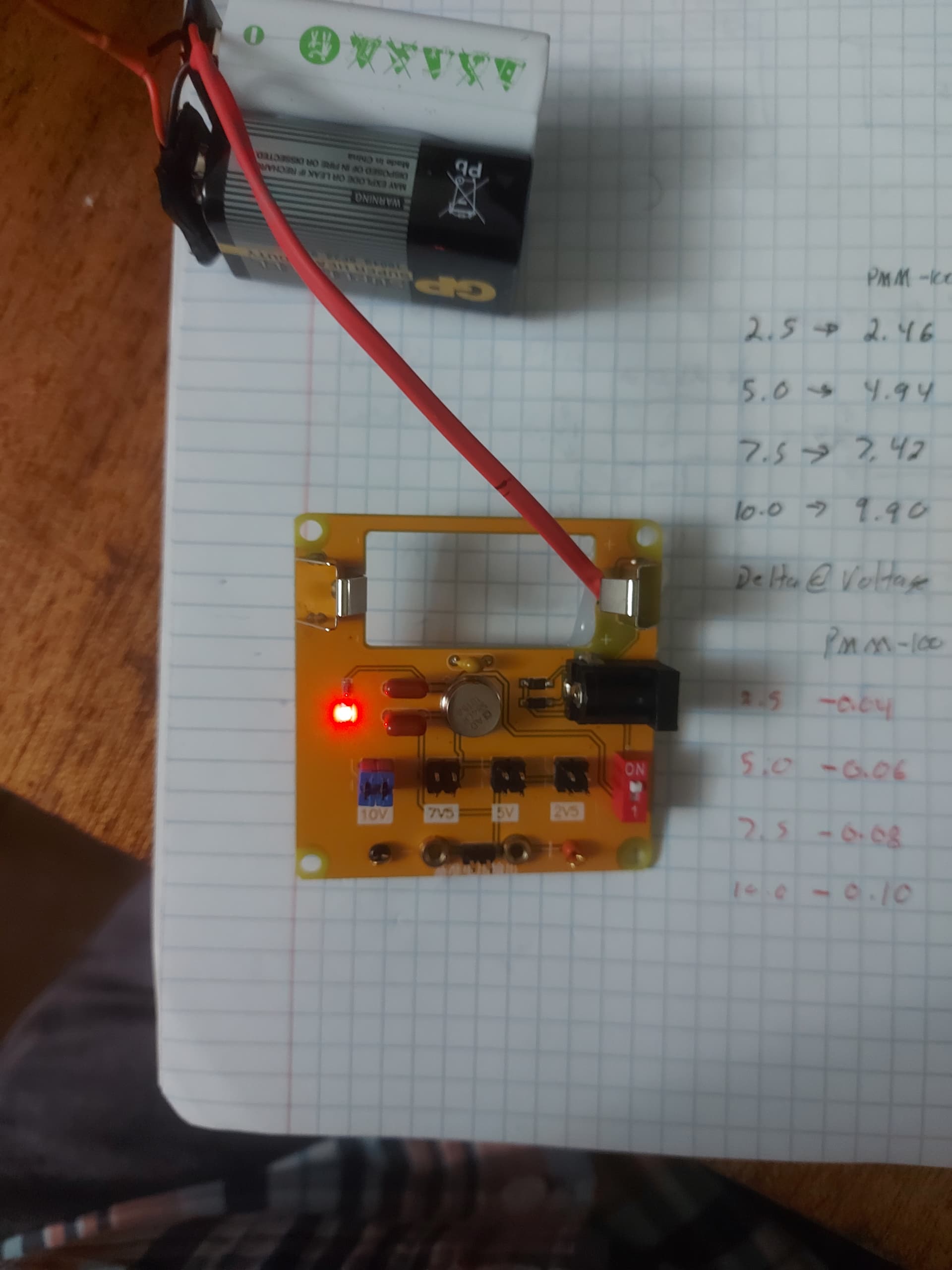
The precision DC voltage reference:

  • Vcc = appx. 18v.  (two 9v batteries in series)

  • Anything better than about 12v is OK.  I vaguely remember that Vcc maxes out at either 40v or 60v for the Analog Devices programmable precision voltage reference IC
     

I paid less than $10 USD for it from China so I can’t complain.  Maybe it’s not good enough for a HP precision Ceasum Atomic Time Standard, but it’s good enough for me.

It provides the following standard voltages based on jumper settings:

  • 10.00

  • 7.50

  • 5.00

  • 2.50

====================

First:
I went to Chip and Dip and measured the voltage reference with their Fluke DMM.  They assured me that the meter was probably more accurate than my reference.  Even if that’s not precisely true, I accepted as true that it was likely better than my el-cheapo DMMs.

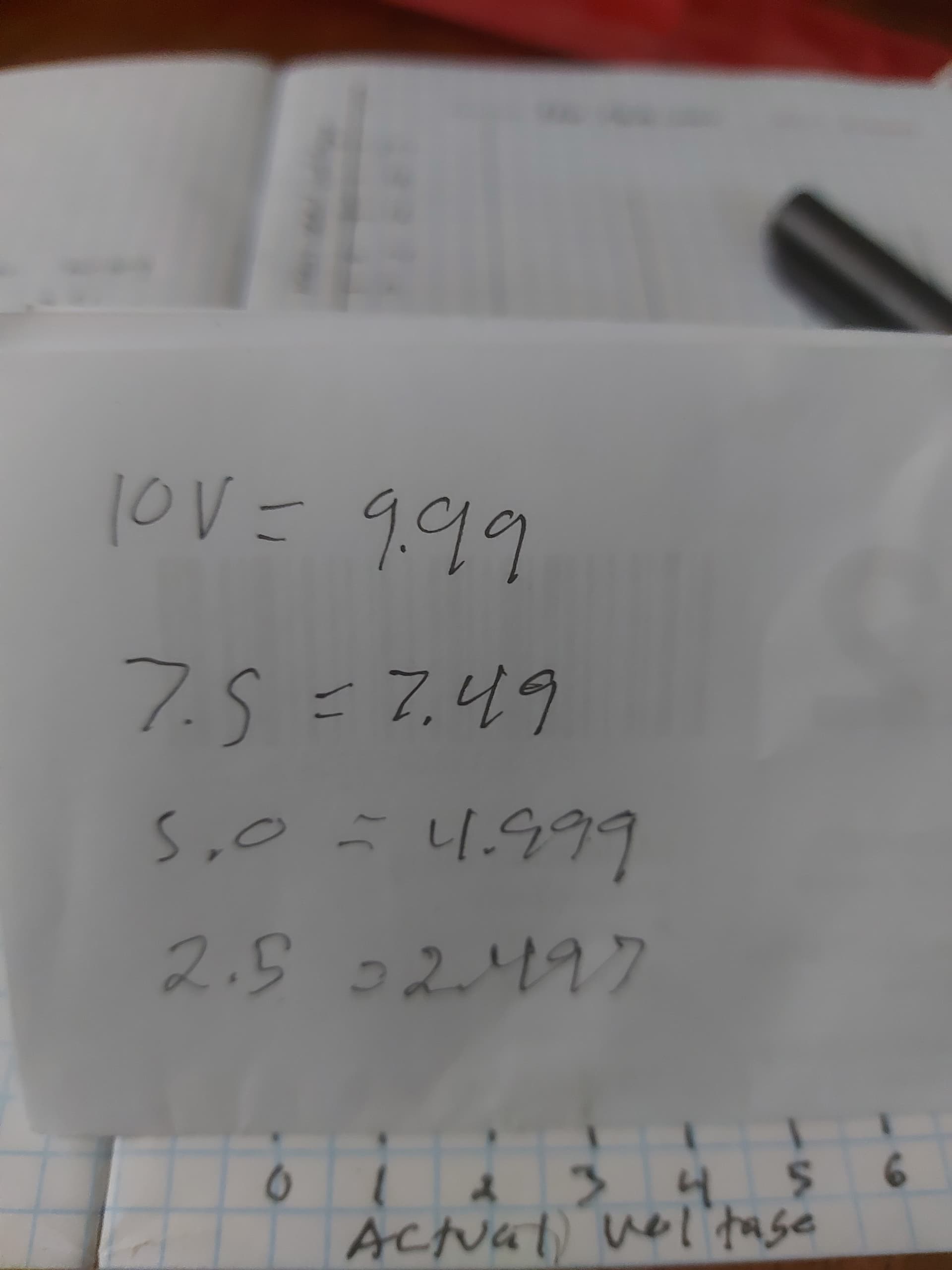
The measured voltages using the Fluke DMM:

  • 2.50 => 2.497

  • 5.00 => 4.999

  • 7.50 => 7.49 (change in precision)

  • 10.00 => 9.99

Rounding to 2 decimal digits the difference was so small I decided to round to even voltages.

====================

Then, I measured the reference voltages with my two DMMs

  • A PMM-1000 DVM I bought somewhere.

  • A MT-009 Auto ranging DVM I bought from Bangood.

Measured voltages:

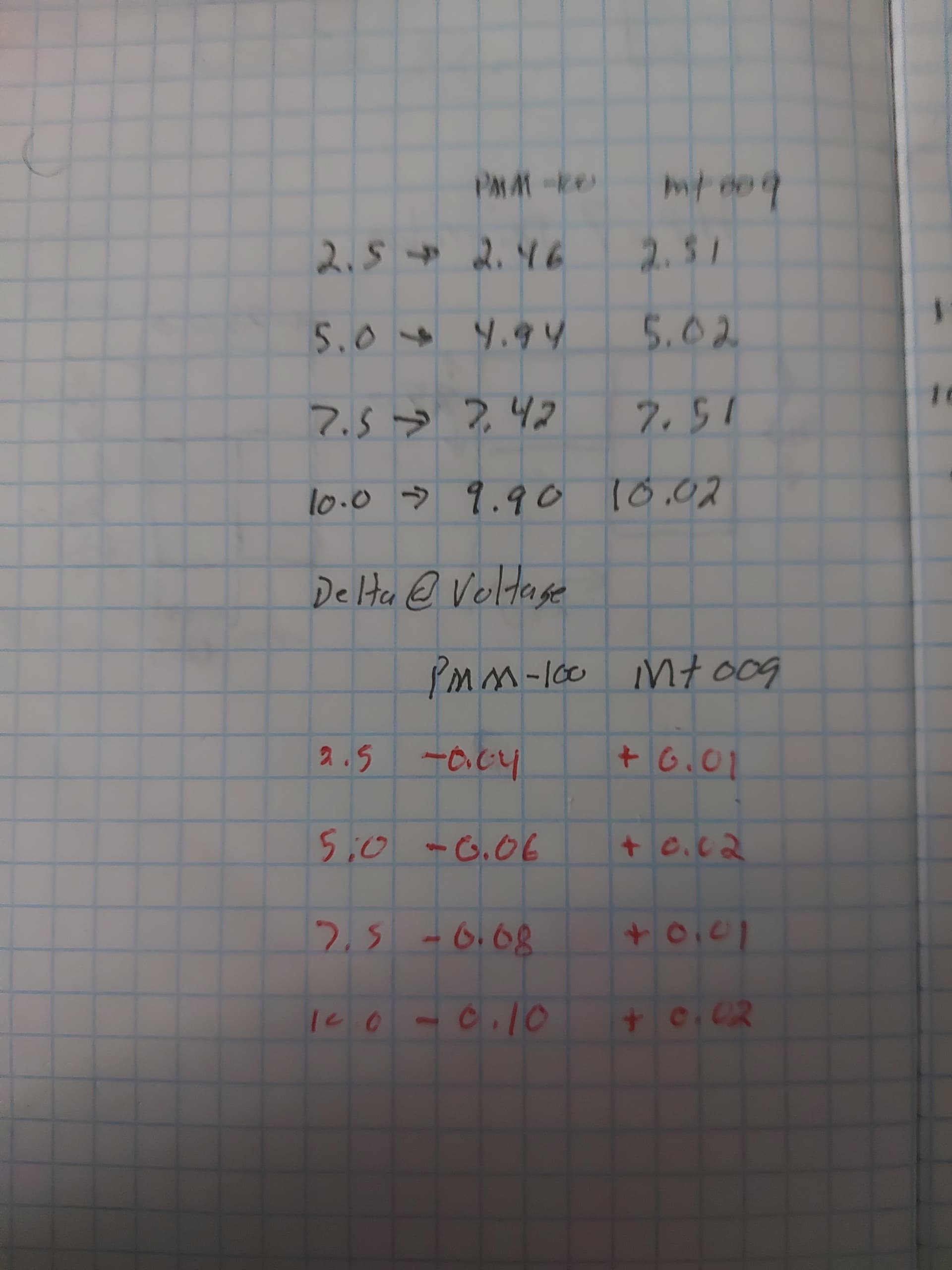
1.  PMM-1000 DVM       delta
    *  2.50 => 2.46   - 0.04
    *  5.00 => 4.94   - 0.06
    *  7.50 => 7.42   - 0.08
    * 10.00 => 9.90   - 0.10
Measured on the 20v scale

2.  MT-009 Auto ranging DVM
    *  2.50 =>  2.51   + 0.01
    *  5.00 =>  5.02   + 0.02
    *  7.50 =>  7.51   + 0.01
    * 10.00 => 10.02   + 0.02
Allowed to auto-range automatically
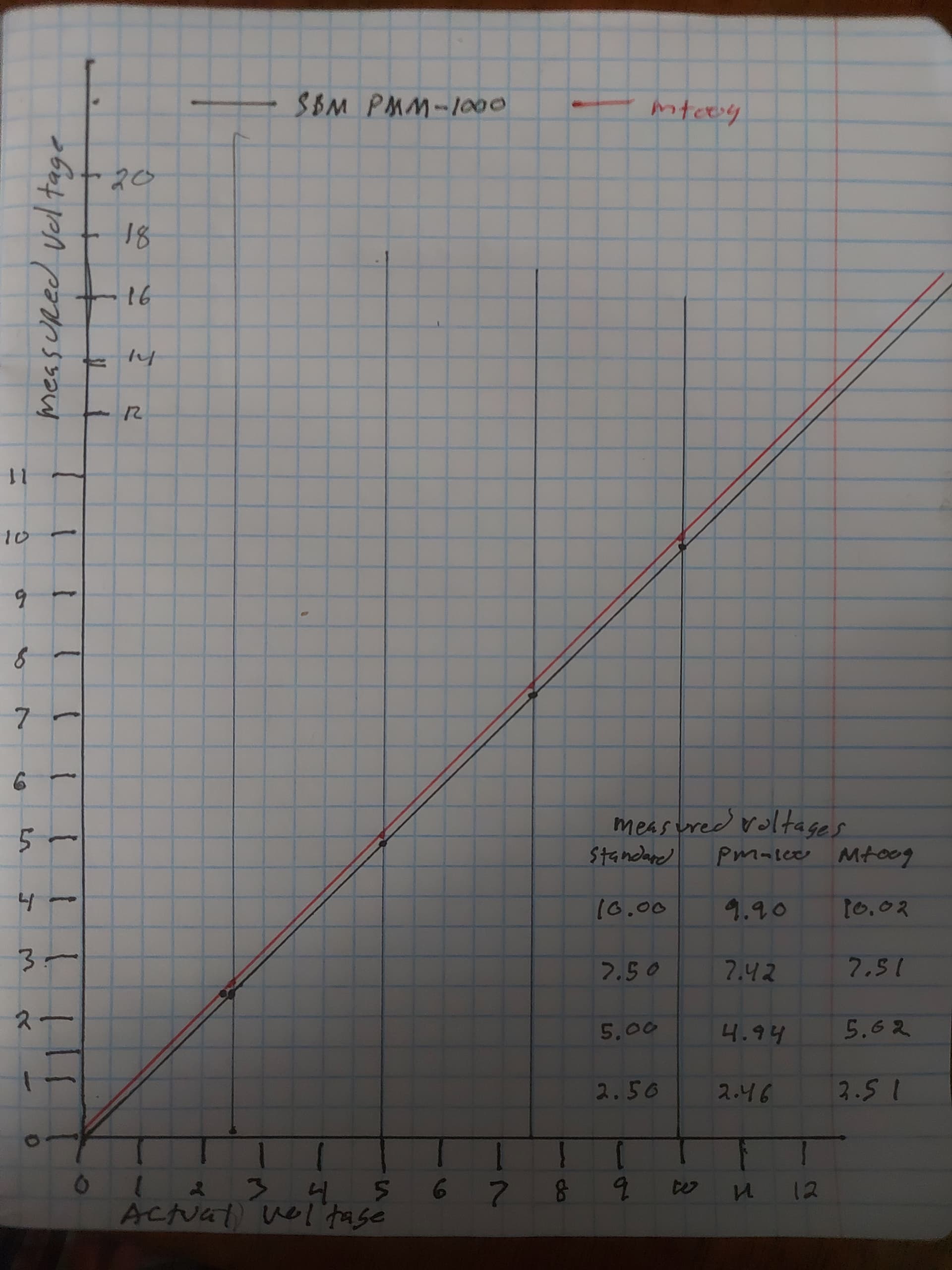
The conclusions:

  1. The PMM-1000 has a linear - 0.02v offset per 2.5v. (zero appears to be right on the mark so it’s a gain offset at the high end.)

  2. The MT-009 DVM appears to have a constant + 0.015v offset throughout the range of the voltage standard as noted by the last digit flipping back and forth.


With this data I can begin to calibrate the adjustable supplies on the bench power supply.

====================

Next steps:

  • Calibrate the variable voltage outputs on the bench supply.

  • Standardize the value of some high power resistances I bought.

  • Use these resistances to calibrate the current scale on the variable voltage outputs.

2 Likes

better tolerate the variable-less-than-five mili-volt differences I see between the average of three “diode drop adjusted EasyGoPiGo3.volt()” measurements, and the average of three INA219 supply side measurements, and my eyeball average of the inline jumping volt/current/power display when occasionally inserted at the battery.

The Raspberry Pi presents such a wildly variable load to the GoPiGo3 power circuit. I cannot tell if the GoPiGo3 supply circuit diminishes or amplifies the variability. Crazy that peak load from a Raspberry Pi at idle can vary by 2W from the average.

2 Likes

Believe it or not, (IMHO/AFAIK), that’s expected.

Switching transients and the number of internal circuits active at a particular instant in time can make both. . .

  • The power supply rails quite noisy,
    – AND –
  • Cause the instantaneous power draw to vary over wide limits.

When I was working with designs using the venerable 8080 processor “back in the good ole’ days”, one of the most emphasized parts of the Intel 8080 databook was an entire, (large!), chapter on power considerations - how to keep the rails quiet and how to make sure the power supply could source enough reserve current to keep the 8080 from going bonkers.

At least 1/2 of the passive components that were on a S-100 buss processor board were for power rail filtering to keep digital noise down to acceptable levels.

I was involved in several processor based design projects that I tossed back to the designers with the comment that they should re-read chapter “X” in the databook.

Engineer - How do you possibly know all that?
Me - [trying not to sound snarky]  I can read. . .

More advanced processors have made that problem even worse.

In fact, a large fraction of the components on a modern PC motherboard are power supply, regulation, and filtering related.

Modern motherboards bear a strong resemblance to a power supply with multiple voltage rails, many high-powered regulator circuits, and large handfuls of active load monitoring and noise suppression circuits.

The number of components that actually do “the heavy lifting” is relatively few - most of which are built into the processor chip or a few motherboard controller chips.

The fact that the Raspberry Pi, (especially later versions), can be noisy and can bounce its power requirements all over creation does not surprise me at all.

That depends on how well the GoPiGo controller sources current.

It’s important to remember that the original GoPiGo was designed around the Pi-2, and the GoPiGo-3 was designed around the Pi-3 before the 3B and the 3B+ existed.

Later Pi versions draw much more power than the GoPiGo controller was ever expected to supply - and that’s why I installed auxiliary voltage supplies to supply power to the Raspberry Pi board itself to reduce/prevent power supply fold-back and prevent the resulting voltage droop.

If the supply can’t source the required amount of power, circuit instability is virtually guaranteed.

2 Likes

And now Dave with a Pi5 wanting a steady 8W at 100% CPU is somehow being fed without triggering the low voltage throttle by that GoPiGo3 power design. I really did not expect it to support “Give it all you got” operation.

2 Likes

:person_shrugging:

Maybe it’s because of all the insert-remove cycles on Charlie - I haven’t found a 40-pin IDE ZIF socket yet - and there might be some contact problems, though I haven’t been able to measure any voltage drop across the connector.

2 Likes

One last thing:
“At idle” is a myth.  At least since DOS 6.22 there’s really never been a situation where the processor is truly idle.

There is so much going on what with internal housekeeping, managing page swaps, keeping all the filesystem tables up to date, waiting for user input and the million-and-one other things that happen behind the scenes, (networking anyone?), that it doesn’t surprise me that the power draw is all over the place.

The Broadcom graphics chip in the processor not only handles the graphics, but acts as the master scheduler for the processor chip and arbitrates access to RAM, ROM, and all the other peripherals like USB and HDMI.

All of this, running in parallel, is going to produce a lot of noise and variable power draw.

2 Likes