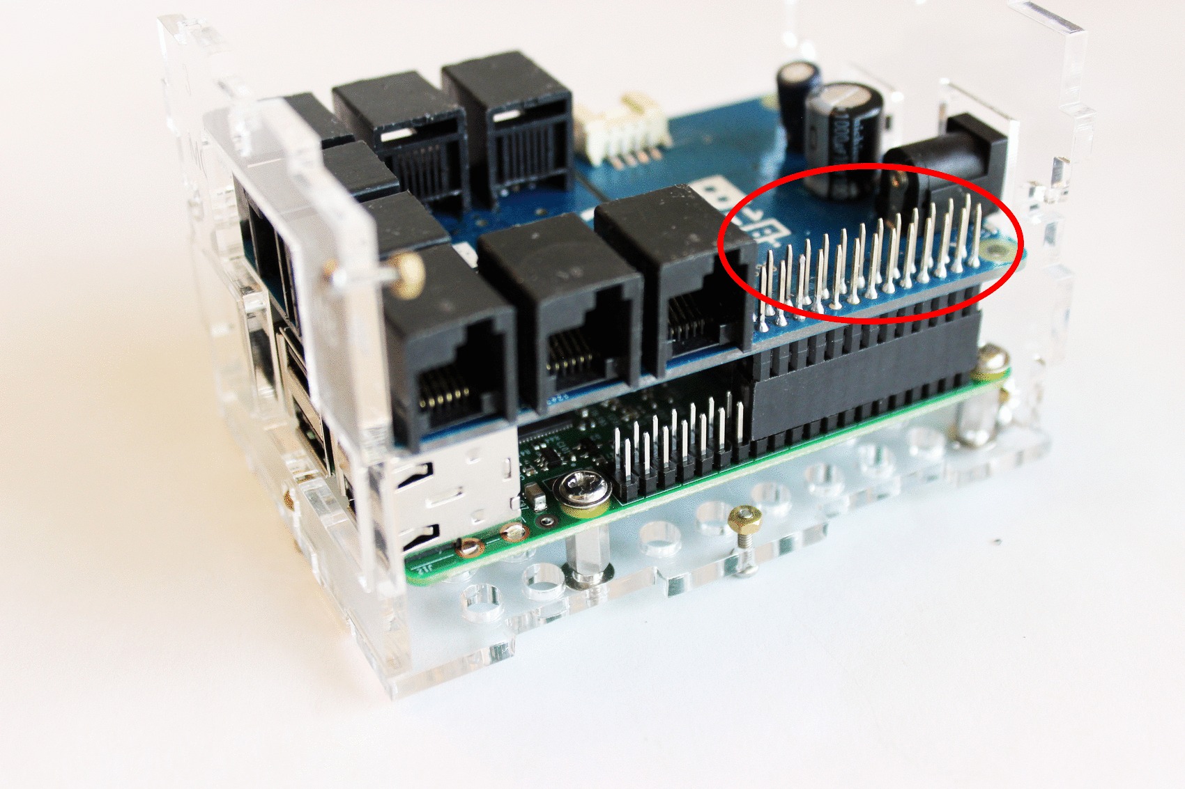
I’m new to electronics so sorry if this is a stupid question. But I am wondering if the 26 pins (circled out below) exposed by the BrickPi can be programmatically used. If they can, is there any example? Thanks.
I’m new to electronics so sorry if this is a stupid question. But I am wondering if the 26 pins (circled out below) exposed by the BrickPi can be programmatically used. If they can, is there any example? Thanks.
Any ideas? I am guessing that the 26 pins exposed by BrickPi are parallel circuits so are (sort of) pass-through of the RaspPi pin 1-26. Is this correct?
@weilin1990
Apologies for not answering sooner. You are indeed correct. Those pins correspond to the underlying Pi pins.
They are available for use.
cleo
Thanks for the update. But if these pins are directly accessed, won’t they interfere with BrickPi?
Concretely, I now have the BrickPi sitting on top of Raspberry Pi pin 1-26, controlling two EV3 motors. I also have a HC-SR04 sensor. If I connect trig and echo to GPIO 7 and 8 to the pins exposed by BrickPi (not RaspPi), will BrickPi still work properly?
Alright I found this post and then the pic below from the schematics file.
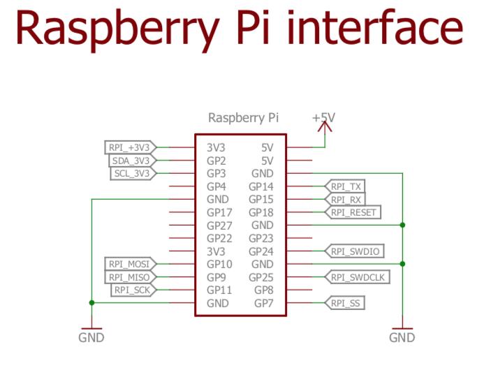
Is it the case that all the pins that have no green outgoing connections, (i.e. GP4, GP17, GP27. etc,) are available for use and passed through directly to the RaspPi?
All 26 pins are directly pass-through. You can use any of the GPIO that the BrickPi3 does not use. This includes GP4, 8, 17, 22, 23, and 27, as well as the GPIO pins on the 40-pin header that aren’t passed through the BrickPi3.
You can still use the I2C bus, as the BrickPi3 just provides pass-through (with level conversion) to the Grove I2C port. The RPi I2C bus runs at 3.3v, and the Grove I2C system runs at 5v.
The UART lines (GP14 and 15) are connected to the BrickPi3 microcontroller, but aren’t used for anything currently, so you can still use them. It’s unlikely, but in the future, these could be used for communication.
The SWD lines (GP24 and 25) are used for flashing/updating the firmware, but they are available to connect to and use when you aren’t flashing the firmware.
GP18 must be left alone, as it is connected to the BP3 microcontroller’s reset pin.
GP7, 9, 10, and 11 are used for communication between the RPi and the BrickPi3.
Pin 1 (RPI_+3V3) is used by the BrickPi3 only as a voltage reference for the RPi I2C bus.
Pin 2 (+5V) is used to power the RPi, and can back-feed USB power from the RPi to the BrickPi3 when you aren’t using batteries to power the BP3. Powering through the RPi USB port without battery power, you can use any sensors, but no motors.
Matt
So for example you can’t put the pi Motorshield on top of the brickPi?
Is there a shield you know of (apart from another BrickPi) that can go on top and provide more access to more motors?
This is true only if they don’t use the same control pins.
For example, if the Brick Pi uses the SPI pins[1], you cannot use them as they are not multiplexed. (ask how I know!)
If the new board:
THEN you can use the external board with the Brick Pi.
==================== Footnotes ====================