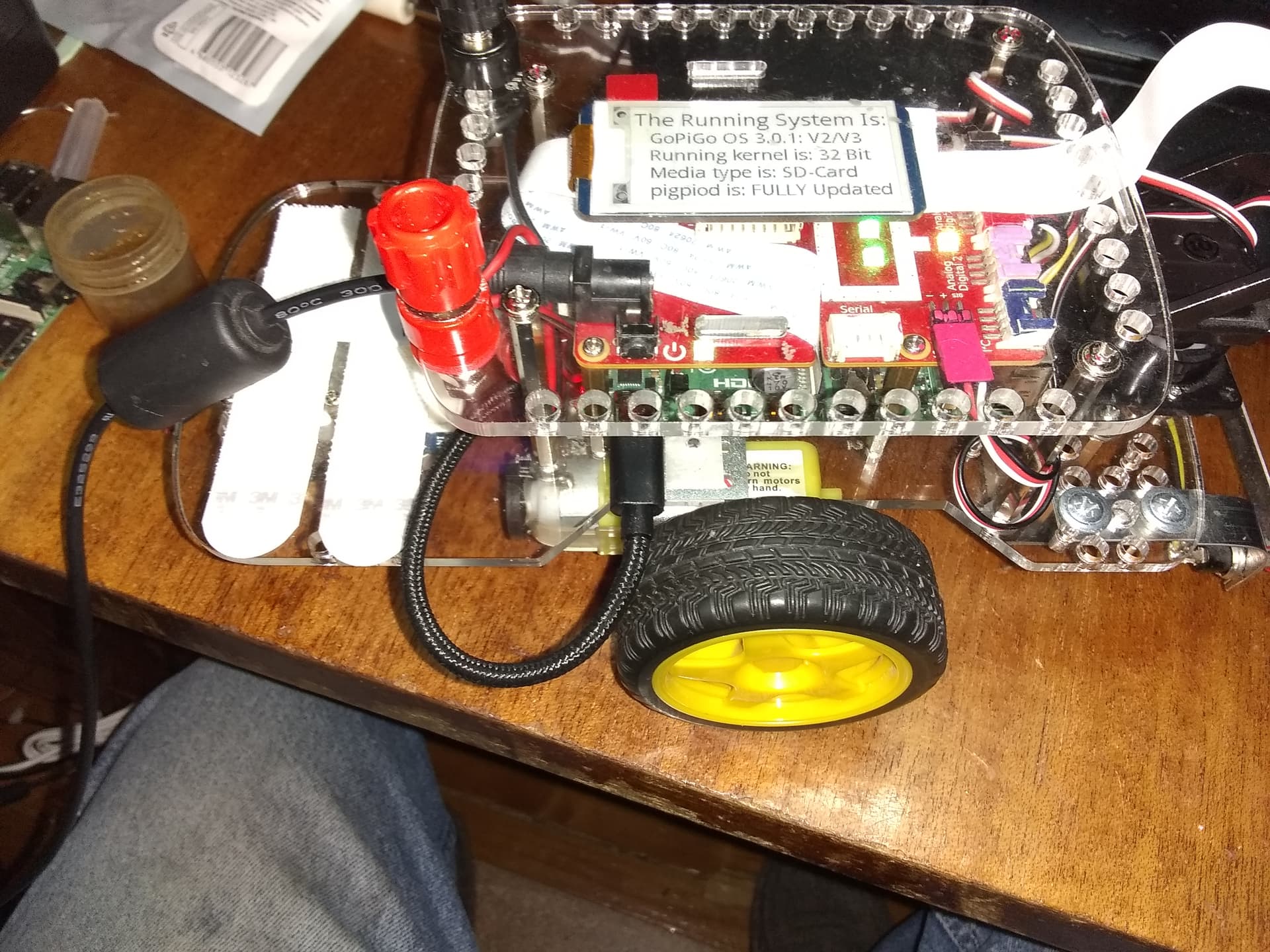
Today I found a (relatively) inexpensive USB-C cable that I could use for an auxiliary power source for Charlie, (and taking a page out of @cyclicalobsessive’s play-book), I wired up a buck converter from the battery terminals to the USB-C connector to provide an additional 5v power source.
Hopefully this will prevent power drooping during intermittent heavier than normal loads.
Viz.:
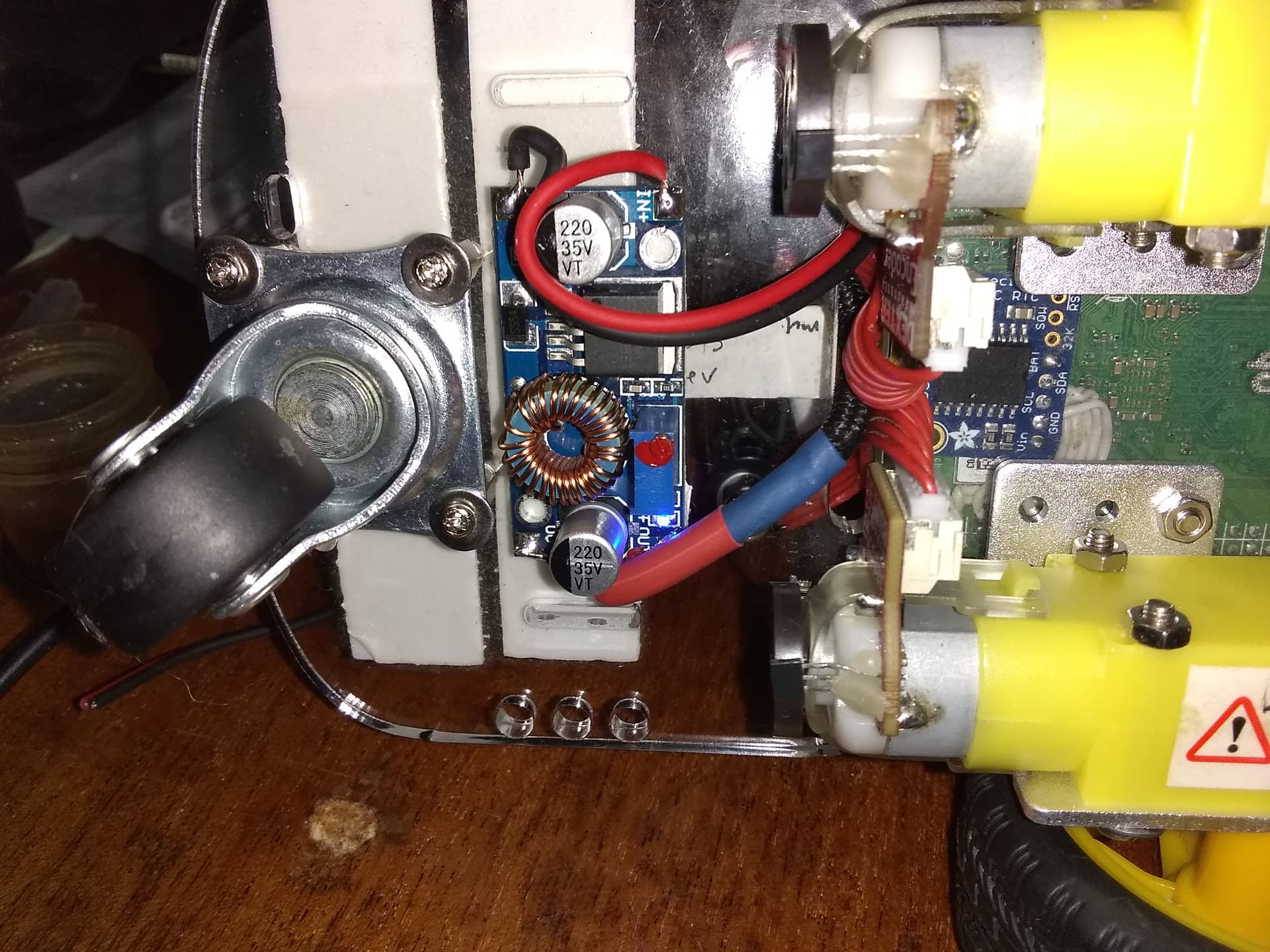
Charlie’s new buck converter, attached to the bottom near his rear caster.
What I mean by that is to adjust the voltage output of the converter to match the voltage of the GoPiGo3 board. this allows them to contribute power equally.
What I did was slightly different:
I measured the 5v with an Official Raspberry Pi-4 external supply attached, and then without.
With the external supply attached, the 5v measured almost 5.2v and without about 5.0 - so I adjusted the buck supply to provide the 5.2v the “official” supply provided.
This “over drives” the GoPiGo’s supply so the external supply provides the lion’s share of the 5v power, allowing the GoPiGo’s board to provide an increased amount of 12v power to the circuitry that needs it.
Should the external buck converter droop for whatever reason, the GoPiGo will pick up the slack.
The one thing I don’t like is that neither of the supply outputs are diode isolated so, theoretically, one supply can back feed power to the other which is not good.
However, since it is not possible to exactly balance the load-sharing between the two supplies without significant modifications to both supplies, I decided to imitate the action of the external Raspberry Pi supply.
What I am hoping happens is that with the output of the buck converter set higher than the GoPiGo’s 5v buck converter, the GoPiGo’s converter will detect a higher than needed voltage and shut down because it doesn’t need to supply additional power.
The result should be that the VCC voltage rises slightly because it is not providing power to the 5v circuitry anymore, (or is providing only de minimus power to keep the circuit alive) - which is exactly what appears to happen because the VCC voltage does rise slightly when I overdrive the 5v rail.
This should allow the excess battery power to provide extra power to the GoPiGo circuits that need it.
I knew that the Pi4 was using USB-C and after rev 1.2 was “power delivery compliant”, but had not heard that USB 3.x had actually re-spec’d the USB-A 2.x 5v tolerance. I had been thinking “power delivery” was all about allowing higher voltage (9v, 12v, 20v), and did not expect the 5v tolerance to be loosened.
This is good news, and finding out the Pi3B+ has the same power management chip as the Pi4 adds one more benefit of the plus over the “little sipper” 3B.
I was pretty settled with the Pi3B non-plus being the best Pi for the GoPiGo3 from a power usage / processor performance standpoint so felt a bit awkward when the GoPiGo3 kit changed to include the Pi3B+.
I thought the only important benefit was the addition of 5GHz. Allowing 5.2v even up to 5.5v is great.
My understanding of “power delivery compliant” was that it could signal to “smart” power supplies the voltage it wanted, falling back to 5v if not possible, or not accepting power from that source.
5.2 seems a bit high to me too, but I have not taken the time to check the other Pi-4 supplies I have.
Now that you mention it, that’s a bit disconcerting to me as the +5v rail should be pretty darn close to 5.00 volts, and tightly regulated to that value. Maybe today’s chips are a bit more “loosey-goosey” with their power spec, but it’s still puzzling and disconcerting.
I will have to research this further - thanks for “poking me” about this, I had totally glossed over that aspect.
I discovered that the spec’d input voltage to the Raspberry Pi’s power connector is 5.1 volts, with no tolerance mentioned. There is also no mention of the 5vvmax rating for the device, nor the maximum voltage rating for the internal 5v buss.
Note that this link DOES have charts detailing typical and maximum current ratings for the various devices.
Strange responses there. You saw 5.1v as the nominal Pi4, and I saw even higher tolerance on Wikipedia. That 5v +/-5% answer seems to be either old or over-simplified.
Worst-case voltage drop topology of a USB 2.0 host to low-power device chain, at steady state
The tolerance on V_BUS at an upstream (or host) connector was originally ±5% (ie. could lie anywhere in the range 4.75 V to 5.25 V). With the release of the USB Type-C specification in 2014 and its 3 A power capability, the USB-IF elected to increase the upper voltage limit to 5.5 V to combat voltage droop at higher currents.[41] The USB 2.0 specification (and therefore implicitly also the USB 3.x specifications) was also updated to reflect this change at that time.[42]
This is all at the connector end of the interface and there it doesn’t matter if they spec 5v or 500v. What matters is what the chips are spec’d for on the 5v VCC rail and how the input voltage relates to that.
As I am sure you know, using a standardized connector, especially a power connector, implies some degree of conformity to the standard itself.
It’s like having a house full of North American parallel blade mains sockets on the wall, and wiring them up with 220v, 50hz mains power. You are just ASKING for trouble.
In fact, the USB standard even specifies a “standard” way of advertising that you are not a “standard” device - which they don’t bother to do.
Self-appointed experts with high post numbers, that don’t point to their sources.
It is interesting that the official power supply publishes more detailed power specifications than the official Pi4 specification that it powers.
Sometimes specs really surprise me though, like this one from that Pi4 power supply:
I am already feeling out of control every night when I walk into my bedroom, throw the wall light switch, and there is a noticeable delay before the (3-way LED) light illuminates my world.
My Mac Mini, (located under my desk, shrouded in darkness with no tactile feedback on the power switch, and no power LED) gives no indication, while I am waiting on my knees under the desk, that I have succeeded to turn the computer on for several seconds while it starts its boot sequence sufficient to grace me with an “ahhhhh” sound clip.
How many times do we click on a website button and get no feedback that the computer is even aware that it exists for our pleasure not for the economic stimulus to society?
I just expect too much out of product development. The real problem is me. Wanting to know the tolerance on the supply voltage on a $100 computer? “Leave those details to us…”
When this “$100” computer is being marketed to the maker space and it’s even being pushed for industrial applications - “power supply tolerances” is not a trivial question.
It is times like this when I begin to understand the character John Adams in 1776, where he said: “I have such a desire to knock heads together!”
We’re not talking about a macbook or an ipad, we’re talking about a naked board, with a connector that is “USB-C” in name only, where they wont publish schematics of key parts of the board - and the ones that are published are woefully out of date. . . .
We should not have to go begging on our knees and lick the bottoms of their feet for basic technical information about the PCB we’re using.
One thing does puzzle me:
The name “USB-C” is a trademark and is copyright by the USB Implementation Group, (or whatever they call themselves). They should do something to regulate how this is used:
The Raspberry Pi Foundation won’t allow you to call something a “Hat” unless you meet certain very specific criteria - and they get really fussy if you do.
The HDMI people won’t allow you to use the name “HDMI”, or call your video port an “HDMI” port unless it conforms to extremely rigid specifications, you pass muster with them, and you get a license to use their interface protocol and connector types.
Why does the USB group allow their “brand names” and connectors to be used by anyone, doing whatever they want, in whatever way they want? This is where all the confusion comes in - they, (the Raspberry Pi people), call it “USB-C” but it isn’t really - as far as they’re concerned, it’s just a metal shell and four wires that happens to be in the shape of a USB-C interface connector. If you take them at their word, and plug a USB power adapter into it and something catches fire or someone dies, it just vacuum’s being you if you didn’t use their preferred adapter.
More important than that is, how does the Raspberry Pi Foundation get the chutzpah to absolutely demand that people meet their specification, and then spit on everyone else’s?
</rant>
Though the article admits that “getting USB-C right can be a daunting task” - as several comments mentioned, a schematic showing the correct design is provided in the reference implementation. All they had to do was cut-and-paste it.
()
Though to be honest, all of this is rather wide of the point. . .
==============
Ultimately, what I ended up doing was to adjust the output of the auxiliary supply to 5.2 volts.
Super good outcome. Glad to hear that works. Anything that increases the processor : effectors isolation strengthens the system. Even if it adds complexity and cost it turns a minimal design into a maximal design to form a really solid foundation for a long-useful-life robot.
I’ll be interested to hear what effect this robust supply design has on Charlie’s “idle playtime” and “idle battery power consumption” (in Watts at the battery). I’m wondering if one 80% efficient power supply sourcing W watts, is any different than two 80% efficient power supplies sourcing W/2 watts each. Might not be any significant power loss, but then again I was never good at modeling reality.
Are the 5V input on the USB-C and the GPIO bridged and simply reverse protected by the SMBJ5.0A-TR diode, with all the processor and board components running off the U2 - MaxLinear MxL7704 PMIC, (and that other unspecified chip U3 providing 1.05v and 1.0v)?
Yeah - they basically told everyone (and you…) to buzz off:
You tried! What is the significance of that “invalid” tag on your issue?
That has never been an important metric for me - at least for the time being.
Right now I’m following the words of some Unix guru of days gone by, who was talking about premature optimization: “Get it working, then get it right, then get it fast.” Right now I’m working on the “Get it working” part as, IMHO, if it ain’t working, power efficiency don’t mean squat!
I was, and am, curios about the effect of possibly overdriving the output of the GoPiGo board as I remember people who had overheating issues on their GoPiGo’s when external power was also applied.
I want to be careful, but I am not worried as I have been dual-powering Charlie for a while using an external Pi-4 power brick.
The problem, as I remember, was confined to one or two latest rev GoPiGo3 boards and may have been a board defect as it was never really characterized.
“Ouch!”, is right! GoPiGo spare parts simply don’t exist here. Not to mention that you should warn us about “land mine” puns!