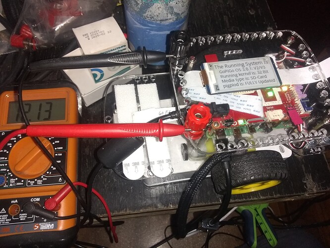
How quickly can you read the GPG battery voltage and get valid results?

Sounds like either the dining hall should have been condemned or you were having a good time. :wink:  At least it wasn’t a :clap:.

If I remember correctly, (shrug):

  • “mean” = “average” = sum_of_all_samples / number_of_samples
  • “median” means the same thing in statistics as it does in driving:  It’s what’s in the middle.
    • In the set “12345” the median is “3” because that’s smack-dab in the middle.
    • In the set “123456” the median is “3.5” because that’s in the exact center of the sample set.
  • “mode” represents the value, or group of values, that shows up the most often.
    • If you have a reasonably large sample of numbers, and there is a bell-curve distribution around “15”, (15 occurs the most often, other numbers around it less often tapering as you move away), and there is a few samples in the 500 range, both the median and the mean will be skewed way north of “15”, but the mode will be “15” because that’s the value that occurs the most often.
    • In the census of a reasonably large population, (say in Detroit), you might get a lot of racial types distributed around “African American”, another whole bunch around “Caucasian”, with a smattering of other racial types filling in the cracks.  This would be considered “multi-modal” - as there are two distinct types that occur far more often than the other types.  This is the kind of demographic data that advertisers live for. (:wink:)
  • Ideally, if the sample is reasonably large, and things are distributed well, then mean, median, and mode will be centered around the same small set of numbers in your sample.  This tells you that your sample is both homogeneous and well distributed, resulting in a high level of confidence in the outcome.
  • “sample size” represents one of the factors used to determine if the level of confidence is worth spitting on or not.
    • In a group of two million individuals, a sample size of “fifteen” doesn’t lend itself to credibility.
    • Determining what size the sample must be to be believable is a whole 'nother can of worms.

When dealing with statistics, just remember the words of the famous mathematician and philosopher, Renee Descartes:

Wikipedia has an interesting article on its origins, attributing it to numerous people, including Mark Twain and Benjamin Disraeli.

:+1:

2 Likes

statistics.mode(values) will spit that out

1 Like

The 60 and 66 measurements are at 1.0 second and the 601, 602, and 663 were at 0.1 second:

pi@Carl:~/Carl/Examples/voltagereadspeed/orig $ more voltage_test.txt 

We took 60 measurements and the average differential was 2.684
(based on an input reference voltage of 12.0)

We took 601 measurements and the average differential was 2.692
(based on an input reference voltage of 12.0)

We took 663 measurements and the average differential was 2.699
(based on an input reference voltage of 12.0)

We took 66 measurements and the average differential was 2.707
(based on an input reference voltage of 12.0)

We took 60 measurements and the average differential was 2.713
(based on an input reference voltage of 12.0)

We took 602 measurements and the average differential was 2.716
(based on an input reference voltage of 12.0)

1 Like

The one thing you need to do is measure and set the reference input voltage so that the differential values make sense.

I have no idea where these measurements came from as they don’t appear in the data.

Oh snap! That’s the number of measurements taken!
[cartoon curse words!]

1 Like

Don’t have a way to do that really, especially not to a 3-digit precision. The 3-digit precision voltage measurement at the battery jumps around too fast to read on my meter.

I looked in my junk drawer for a decent power supply, but all were either too weak or too high voltage.
I don’t often need a solid variable voltage supply but that and an oscilloscope have always been on the want list but never make it to the top of list.
Besides, us “software guys” can’t be trusted with tools - union rules when I worked for Lockheed-Martin Marietta. I’m surprised they didn’t flag me for pulling out my own desk chair.

2 Likes

Question: Lacking an oscilloscope, if I put my multimeter in AC voltage mode and measure across the battery under load, will the multimeter read the load induced voltage variation peak/rms in mV?

Using the reading at the start of the test, probably should use an average of ten reading as the reference, but using the reading at the start of the test as the reference and testing for a short time so that the battery voltage should not decrease very much during the test, should measure the GoPiGo3 systemic battery voltage reading variability. Matt was saying the readings were +/- 4% accurate which is a whopping +400mV to -400mV at 10V with an 8.6mV precision and with the 5v as the reference. Watching your printout of the 5v reading against the 5v reference claims the 5v is varying by around 70mV, but then asking the fox how many chickens are in the coop is probably just as foolish.

At any rate: Running with mode output shows that the most probable reading if you only take one reading is probably not near the median/mean/average or what ever that “add em up and div em out” number is:

We took 60 measurements at 1.0 seconds (based on reference voltage of 8.917)
min: -0.180  max: 0.077  mean: -0.134  mode: -0.155   sdev: 0.056 

We took 60 measurements at 1.0 seconds (based on reference voltage of 8.952)
min: -0.137  max: 0.026  mean: -0.098  mode: -0.120   sdev: 0.041 

We took 601 measurements at 0.1 seconds (based on reference voltage of 8.926)
min: -0.171  max: 0.129  mean: -0.115  mode: -0.137   sdev: 0.047 

We took 602 measurements at 0.1 seconds (based on reference voltage of 8.909)
min: -0.188  max: 0.112  mean: -0.129  mode: -0.154   sdev: 0.048 

2 Likes

Probably not.

What you will get is the AC component of the DC voltage - i.e. the ripple voltage.

The question of if you get a simple average, P/P, or RMS is a question for whomever wrote the software/designed the hardware for your meter.

Assuming that you don’t have a MULTI-hundred-dollar Keithley, Fluke, Techtronics, or such like meter accurate to God’s Own Left Toenail, (i.e., not an el-cheapo WallyWorld meter like mine), then it’s anyone’s guess.  I suspect it would be accurate to, (ahem!), “commercial” standards, but what those standards are is a mystery to me.

Like you, a set of precision voltage references, calibrated resistors and current shunts hasn’t reached the top of my “Holiday Gift List” either, though a reasonably precise digital scope with a minimum of a 30 mHz bandwidth should do as a voltmeter, if the people who wrote the software have a clue. :man_facepalming:

On a similar front, I am working on trying to figure out how to turn the JYE DSC-068 'scope I have into a respectable USB scope on Win-7 or XP.  I was able to find an older laptop to experiment with and I have the remnants of my TechNet subscription’s downloads and keys, so once I get a moment or two, I am going to mess with this.

A Saelae logic analyzer (that plugs into your laptop/desktop) is on my list too, but I think I’ll get back to the States before I have even the Ghost Of A Chance of getting one.  They weigh-in at the cost of a laboratory grade meter or so, and that’s just not in my budget until that federal grant to invent something comes through. (yea, right!)

2 Likes

Update:

I have test results from my battery test.

  1. The software used:
    batt_test.py (4.6 KB)

  2. The test configuration:


    I added binding posts to the robot itself and connected them across the barrel connector with (relatively) beefy wire to eliminate errors due to line drop.

  3. The tests:

    • There were two test series, one with the big power-supply I built - and discovered that the leads to the barrel connector I used are too small - and the other with a multi-amp 12v power brick.
  4. The results:

    • Power supply:

      • 0.25 sec/measurement = 0.511 voltage differential between the measured voltage at the barrel connector and the voltage as-read by the robot.

      • 0.35 sec/measurement = 0.513 and 0.516

      • 0.50 sec/measurement = 0.515

      • Average = 0.514 and the range was 0.005

    • Power Brick

      • 0.25 sec/measurement = 0.512 and 0.512

      • 0.35 sec/measurement = 0.513 and 0.510

      • 0.50 sec/measurement = 0.509 and 0.510

      • The average was 0.511 and the range was 0.004

The overall average is 0.513
t
The range of all the readings is 0.007, though I consider the second set more reliable as the voltage was more stable during the test.

  1. The test data:
    results.zip.txt (2.6 KB)

Conclusion:
I am going to set an offset of 0.512 to compensate for the circuit drops when measuring the battery’s voltage.

1 Like

Yes the wire again. So many people had mysterious power problems the first few years the Raspberry Pi came out that turned out to be the tiny, but significant, voltage drop between an “in spec” power supply and the Pi.

Perhaps measuring at the power supply with the double barrel plug jumper in line to the GoPiGo would be more representative of the batter voltage for particular GoPiGo3 readings?

I think that is why my reading to battery voltage constant is more than the usual diode drop value even on Dave.

2 Likes

I wired the binding posts directly to the barrel connector.

Because my meter is a 20,000Ω/volt instrument, (I hope!), the current draw through the meter should be negligible and the voltage reading there should be accurate.

Since what I am hoping to achieve is an increase in the accuracy of the “measure battery voltage” routine so that it accurately measures the battery voltage, that should be sufficient.

IMHO, (from a hardware engineering standpoint), the fundamental problem is that the Raspberry Pi has “outgrown” the GoPiGo - and current Raspberry Pi versions draw considerably more power than the original model 1 and 2 the device was designed for.

As a consequence, the GoPiGo’s power circuits get overwhelmed and my theory is that the voltage droop can become non-trivial.

I am going to continue examining this issue and I will report findings and recommendations.

2 Likes

Update:

I tried this test with the Li-Ion battery pack and not only is the voltage dropping relatively quickly from fully changed, but there is about a 40 mv variation in the readings.

How do you build on such quicksand?

OK, things settled down a bit - and I ran some tests.

If I modify gopygo3.py, line 616, to read return ((value / 1000.0) + 0.51), I get battery values that are consistent with the measured input voltage.

I also changed my measurement resolution from three digit to two decimal digits - the last digit varies too much to be relevant to accuracy.

Viz.:  (with a measured voltage of 12.13v set into the program)

Test Cycle 1 of 4 which consists of 10 tests every 0.5 seconds)
The Average Differential for this test cycle was 0.0

The Average voltage for this test cycle was 12.13

Test Cycle 2 of 4 which consists of 10 tests every 0.5 seconds)
The Average Differential for this test cycle was 0.0

The Average voltage for this test cycle was 12.13

Test Cycle 3 of 4 which consists of 10 tests every 0.5 seconds)
The Average Differential for this test cycle was 0.0

The Average voltage for this test cycle was 12.13

Test Cycle 4 of 4 which consists of 10 tests every 0.5 seconds)
The Average Differential for this test cycle was 0.0

The Average voltage for this test cycle was 12.13

===================================
The cumulative average of all the test cycles was 0
===================================

Anyone else that wants to try this can, and results would be appreciated.

@cyclicalobsessive
Would you like to try this on Carl/Dave to see how close to the actual voltage measured at the barrel connector you get?

2 Likes
  1. I found: current_Vbatt = egpg.volt()+0.81 to give the most accurate result for both Carl and Dave "at the battery"

  2. I pass the EasyGoPiGo3 object to a helper function:

battery.py:

from easygopigo3 import EasyGoPiGo3

REV_PROTECT_DIODE = 0.81    # The GoPiGo3 has a reverse polarity protection diode drop of 0.6v to 0.8v (n=2)
                            # This value results in average readings vs battery voltage error of +/- 0.03

def vBatt_vReading(egpg):
	vReading = egpg.volt()
	vBatt = vReading + REV_PROTECT_DIODE
	return vBatt,vReading

def voltages_string(egpg):
        vBatt, vReading = vBatt_vReading(egpg)
        return "Current Battery {:.2f}v EasyGoPiGo3 Reading {:.2f}v".format(vBatt,vReading)

Usage:

import sys
sys.path.insert(1,'/home/pi/Carl/plib/')
import battery
import lifeLog
from easygopigo3 import EasyGoPiGo3


egpg = EasyGoPiGo3(use_mutex=True)
...
current_vBatt, current_vReading = battery.vBatt_vReading(egpg)
# OR
current_vBatt = battery.vBatt_vReading(egpg)[0]
# OR for convenient printing and logging:
data=battery.voltages_string(egpg)
print(data)
lifeLog.logger.info(data)   # example adding a timestamped voltages string to life.log

---
pi@Carl:~/Carl $ plib/battery.py
Current Battery 11.60v EasyGoPiGo3 Reading 10.79v

  1. I’m sorry, but measuring at Carl and Dave’s GoPiGo3 barrel connector is not easily accomplished.
2 Likes

“not easily accomplished”?  <== masterpiece of understatement!

In all seriousness, what I need is both a “Charlie” and a “Charlene”, one for the hard-core hardware lifting and one to do software development on that doesn’t depend on hardware mods.  Or, one that I can migrate successful hardware mods to. . .

Every time I flip Charlie’s red-board over with a soldering iron in my hand, I imagine you cringing while I do it!  (:wink:)

IMHO, (from a hardware perspective), the canonical voltage measurement is the voltage at the barrel connector, (v_batt), or the “12” rail after processing, (VCC), as those are the voltages with the most impact.

In fact, (IMHO again), there should be the ability to take both measurements because the current drain can cause the Vdrop across the active power processing components in the power switching section to become non-trivial.

Additionally, (again IMHO), the Raspberry Pi is beginning to “outgrow” the power capabilities of the GoPiGo’s power provisioning.  What was suitable for a Pi or Pi-2 rapidly becomes insufficient for the later version Pi-3’s or a Pi-4.

As I see it, there are two possible upgrade paths:

  1. Upgrade the power-handling components on the GoPiGo chassis itself.
  2. Provide a method where the existing power handling components can signal off-board components that can handle more power. This way the on-board power switching can provide “enable” signalling to the off-board circuitry.

For example, I have a XL4005 based DC-DC buck converter than can handle a fairly large handful of amps - and I am planning, (eventually) to tie this from the 12v power rail at the barrel plug and bring it to the “USB-C” connector on the Pi to provide a 5v “boost” to help prevent power droop when things are running, (like the servos or a SSD card).

The big issue is that I cannot signal the buck converter to “turn off” when the GoPiGo turns off the robot.  However, I can isolate the Venable pin on the controller IC of the buck converter and tie that to something like VCC or the “power_on” line to allow automatic switching.

The really best solution would be a drop-in replacement for the 12v switching MOSFET and the 5v buck converter IC, that will allow the GoPiGo to handle the power requirements of more modern Raspberry Pi’s.  And yes, I firmly expect that there will be a “Pi-5” out there that will want even MORE power and people will want to plug it into their robots or Grove boards. . . (:astonished:)

2 Likes

You’ve mentioned these “helper functions” in the past.  I am going to have to study this in greater detail to understand it/them better.

Thanks!

2 Likes

Update:

I have added the following to “my” version of the gopigo3.py library file:

def get_voltage_vcc(self):
        """
        Get the VCC rail after the big MOSFET switch and the protection diode

        Returns touple:
        VCC voltage, error
        """
        value = self.spi_read_16(self.SPI_MESSAGE_TYPE.GET_VOLTAGE_VCC)
        return (value / 1000.0)
2 Likes

The Pi4 already started making power delivery to the board more complex by allowing USB-C Power delivery, USB-OTG, and eventually figured out how to properly handle a USB-C data connection also.

The iRobot Create3 robot offers both 3A 5V USB-C power delivery to a USB-C connected Pi-4 and USB-C “networking” with the robot over the same cable.

The new 3000mAh Li-Ion juiced GoPiGo3 with a Raspberry Pi3B+ still wins the “best playtime award” in my book with 4-6 hours of mixed driving/thinking use.

The Turtlebot3 Burger only comes with 1800mAh Li-Ion (and Pi4) for a spec’d “2h 30 min Operating”

The “Official Pi4 Power Supply” delivers 5.1V at 3.0A to the USB-C connector. It will be interesting to see if the upcoming 2GHz Pi4 will be offered with the same power supply or a slightly beefed-up official supply. (The existing C version 1.75GHz Pi4’s draw an extra 100mA when overclocked to 2GHz.)

I am pretty sure the existing GoPiGo3 - Raspberry Pi3B+ is meeting all of the grade-school education market needs (with the exception of a sexy case maybe). The more that high schools try to include some introduction to autonomous driving technology, the GoPiGo3 will show its aged design in power supply, processor choice, and software support.

Sad but “the writing is on the wall” for anyone and any robot to read!

2 Likes

I don’t know about that. . . .

You have to admit that our use-cases for the GoPiGo3 are not exactly “mainstream” - and the folks at MR have really dug in their heels about wanting to focus on the “education” market.

Again, I can’t read minds, and I really don’t know how deep their market share is, so I’m not really qualified to “armchair quarterback” their marketing decisions.

As I see it, it kinda’ goes like this:

  1. If you’re trying to teach robotics in a secondary school environment - a GPG3 and a Pi-3(+) could be your ticket to success.

  2. If you’re trying for a thesis presentation like the last couple of people were, you’re on pretty solid ground.

  3. If you’re trying for a Nobel Prize, string theory, or a whacked-out PhD presentation, you might be stretching it.

  4. DARPA challenge?  BattleBots?  Fuggeddaboutit!

But then again, it depends on yourself, your ingenuity, and what you’re trying to do.

We’ll see.

[sidebar comment]
IMHO robotics, as a hobby, may be limited by definition.

There’s still a lot of room to grow as far as the maker-space is concerned and I don’t see things getting back to the way things were in the 50’s and 60’s as far as making things are concerned.  A lot of that was fueled by a saturated “war surplus” market of cheap but sophisticated equipment from the second world war and Korea in the same way the PC boom in the 90’s was fueled by the fallout of the dot-com bust.
[/sidebar comment]

1 Like

That really is the right thing to do - separate supply path to the processor and to the GoPiGo3.

On my prior bot, I used a 7$ Pololu 10A Pushbutton electronic switch, (that had an open enable), between the battery and the bot supplies. I never did wire up the enable for processor shutdown of all the supplies though - needed a double-E to design an RC shutoff the processor could start in motion on the way to shutting down that would jerk the power off after the processor shutdown.

2 Likes

Huh?

You, the Amateur Advanced Ticket Holder from Days Gone By?

RC shutoffs should be child’s-play!

That’s the idea.  All I need now is a USB-C connector that isn’t either junk or $30 as I’m going to have to hack one end off before the granddaughters confiscate it to charge their phones!

What I really need is a barrel-Y splitter. . .

2 Likes

There is one other option that we haven’t discussed:

Us.

I remember my father teaching me about electronics and such-like when I was a kid, but we were from two different generations and the technology he grew up with, and learned from the Navy during the second world war, was rapidly becoming obsolete.  By the time I finished high-school, I had pretty much exhausted what he could teach me.  (At least with regard to electronics and such - he was a clever old guy and could do things nobody ever imagined!)

Now we are the “old geezers” and modern technology might well be passing us by too.

Today we have high school and undergraduate college students doing things with lane finding and obstacle avoidance on a Raspberry Pi  that would have gotten them classified top-stinkin’-secret a decade or so ago.

Another few years? Who knows!

When my granddaughters get out of school and college, they’ll probably be looking at career paths that don’t even exist today.

2 Likes