Thanks @jimrh for your review. I am glad the batteries have been received are appreciated!
As for the short cable, it is short for a reason. In the classroom little fingers get caught everywhere and pulling the cable or playing with dangling cables is just too attractive - whether on purpose or not. 10 year olds fidget.
So we got the shortest cable we could get, believe it or not!
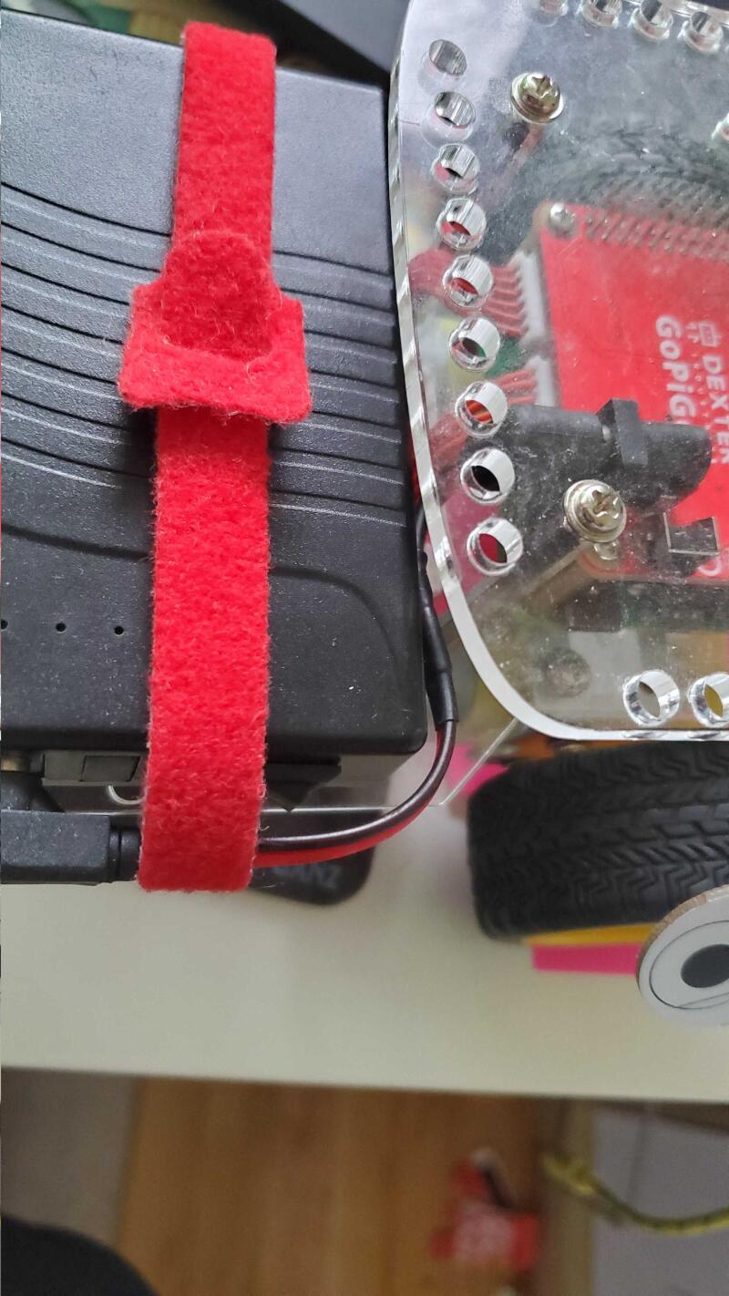
And this is the recommended (at least for the classroom) installation:
Really great point @cleoqc - I know I get so wrapped up in my particular use cases that I forget the target market is actually education. That does change the design thinking quite a bit.
/K
Then something has to be done about the battery’s power indicator.
I have only tried one of the three I received, but when that one dropped to three dots on the power meter - indicating about half of the battery’s charge remaining - it suddenly shut-down without warning. Upon recharge, it started at three dots.
One second it was a happy bunny, the next - dead as a doorknob. No low-power indication on the GoPiGo, no low-power icon, no blinking power dots, absolutely no warning whatsoever. And this is troubling.
Especially in a school environment where the kids may have a tendency to “trust” the power-remaining indication, this could present a problem. If you’re worried about a “fidgety” 10 year old unplugging the battery by mistake, I’d be even more worried about a battery’s power meter that lies to you and allows the battery to die without warning.
Is this normal behavior for the battery? Does the battery need to be “trained” through several charge-discharge cycles for the battery meter to be trustworthy?
I totally agree. Those LEDs are sooo misleading, but it’s due to this particular chemistry. The discharge cycle is such that the battery is very good for a long time, until it’s not. There’s no slow degradation for the LEDs to work.
We are debating asking the manufacturer to remove the LEDs but so far we haven’t made that move.
I was rapidly coming to the conclusion myself that the discharge curve was a “square wave”, so to speak. Just like Wile E. Coyote, everything’s just peachy until you hit the edge of the cliff. . .
I would have thought that, by now, lithium battery makers would have discovered some way to predict end-of-cycle and/or remaining life reasonably accurately.
Update:
I’m seriously considering taking the case off of one of the batteries to see how the manufacturer implements discharge monitoring, what IC’s they use, (if any), and determine if the accuracy can be improved.
Since they advertise overcharge, undercharge, and short-circuit protection, they’re probably using a battery-monitoring-system IC, similar to solutions offered by Maxim. (This one is an integrated battery state monitor IC that can indicate a reasonably accurate state-of-charge.) See below, they’re actually using a much less expensive L6033 lithium battery charge controller IC.
If the manufacturer is using any reasonable kind of battery protection circuitry, there should be a way to get a reasonably accurate battery state-of-charge indication better than “five, four, three, dead”.
This is something you need to discuss with the manufacturer - accurate state-of-charge is not an unreasonable request, especially on a battery like this which is going to be used in a classroom environment as it is essential for the instructor to have a reasonable understanding of the battery’s state-of-charge.
What you really don’t want are teachers starting a class with what appear to be well charged batteries and having them die half-way through the session. If that’s the case, you might as well go back to high-quality NiMH batteries in an 8-cell pack again. At least there the state-of-charge is more easily determined by the output voltage.
First, the battery module is divided into two major subsections:
Three batteries and a charge controller board as a module.
An “output” module that takes the battery’s power via two big wires and provides an on/off switch, a barrel jack, a five-LED “state-of-charge” voltmeter, and an optional USB connection.
The Battery Module:
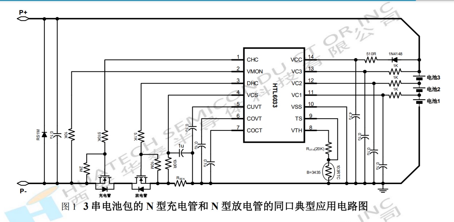
The battery module is based on the Chinese manufactured L6033 lithium battery charge controller chip and a pair of 6630 power MOS-FET transistors connected back-to-back to provide the charge/discharge switching.
It appears the battery module manufacturer lifted their circuit right out of the manufacturer’s “reference circuit” on the datasheet.
Aside from the on-off switch and a few other things, the output interface module is a 5-LED voltmeter based on the very generic LM-339 quad op-amp/comparator and a resistor divider network.
The problem with using such a generic “voltmeter” circuit in this application is that the voltage swing between fully charged and fully discharged, (assuming you don’t over-discharge the batteries), is extremely small - on the order of a volt or two.
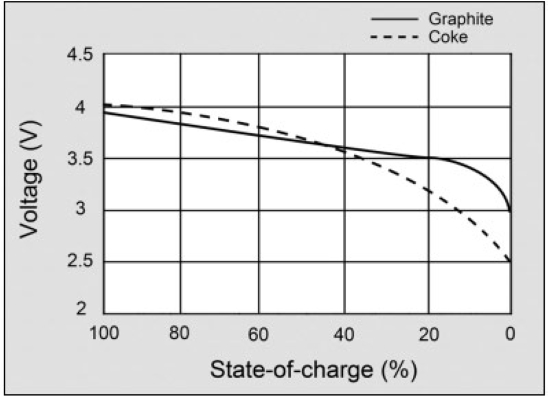
This graph shows the discharge curve of a single Li-Ion battery - a mere half a volt from full to empty! (Ignore the dotted line, that’s obsolete technology.)
Three cells taken together would have a 1.5v drop from full to empty - 12v when full to 10.5v when empty.
Though the LM-339 can be used quite effectively as a battery voltage monitor, (that’s even one of the standard reference circuits for the device), the difference between the “fully charged” voltage and the voltage considered “fully discharged” should be larger than one or two volts, or special adaptations to the circuit need to be provided.
I would suggest against it until you have a better way of indicating state-of-charge.
What I would do is mention that - on this battery - the top three LED’s indicate “Full” - “Half” - “Empty” and that when you get down to the third LED indicator, you’re riding the ragged edge of disaster.
There are probably better ways to use that circuitry more accurately, but I’ll have to do some research on that one.
Update after some additional research and thought overnight:
One thing that CAN be done is to restore the software voltmeter and maybe even update the firmware to provide a “lithium” option that will handle power management to at least some degree via the power LED on the GoPiGo PCB. If the power LED’s on the battery are totally bogus, having at least SOME power-left indication via the power LED on the GoPiGo is better than nothing.
If I get the chance, I will take one of the output modules, carefully measure the voltages at the various LED points, find a copy of its reference circuit, and propose modifications that would cause a better and more linear scale.
Wow - quite the investigation. The voltage/charge curve is really interesting.
The way I have mine mounted I can’t really see the LED’s anyway. So far it’s not an issue - I’ve just run short tests.
As I run it longer I’ll look into writing a voltage monitoring routine, maybe with a shutdown if it gets too low.
Maybe the short term solution is tell teachers just to put tape over the last 2 LEDs as a reminder to just use the first three as you suggest.
Like I’ve said before: Maybe my software skills aren’t so great, but I’ll always put money on my hardware skills.
In this case it wasn’t too difficult once I removed the four screws holding the case together. They tried to hide the part number for the charge-controller IC, but they didn’t try too hard - a few drops of 647 solvent, (which I suspect is a mixture of Xylene and Toluene - also known as model airplane glue), and the black paint came right off. Once I had the numbers for the two primary IC’s, the rest was history.
Unfortunately, the charge controller IC is only manufactured in China, and appears only to be sold to Chinese manufacturers, (there were no, repeat zero, non-Chinese sources of these products), so:
Finding the relevant documentation was not that easy - I was just about to VPN into a Chinese end-point to help my search.
The only non-Chinese reference to this part was a Russian IC look-up site that provided a link to a vendor I had already examined.
Once I found it, all the documentation, (including the data-sheet), was in Chinese and most sites required a subscription to enter. The fact that I found anything appears to be shear luck.
This is one of those situations where Chrome shines with its automagic translation of foreign language web sites and such.
Like programming, if you have any serious experience with hardware design and reading datasheets, you can pick out the relevant information even if “it’s in Chinese” - which it was this time, literally!
That might be a bit of a challenge, depending on the absolute accuracy of the voltage monitor on the GoPiGo - we’re talking a 1.5v delta here - between bung full and dry as a tumbleweed.
Using NiMH batteries, the total voltage swing was something like 4 volts - 12v to about 8v DC - so the need for insane precision wasn’t necessary.
AFAIK, I would want to take a reasonably precise variable “bench supply”, (and an accurate reference voltmeter), and slowly vary the voltage between 12v and low-voltage cut-off on the GoPiGo-3 repeatedly, to determine the “figure-of-merit” for the precision of the on-board voltmeter. (@cleoqc, can you comment on this? Has any research already been done here?)
Once you know what level of precision you can expect, then you will know if it is even possible to write a low-voltage warning/cut-off for the GoPiGo. In other words, do you have enough accuracy to handle a 1.5v delta with any degree of confidence, and a sufficient number of digits of precision to identify exactly where you are on the voltage curve?
That’s the $64,000 question.
(Now all I need is about $300 to get a decent variable bench supply. . . .)
May not be feasible. I’ve used the function call to get the voltage from the GoPiGo-3 board, but I haven’t done any testing on how accurate and stable the readings are. Even if it’s not accurate in an absolute sense, if it’s stable and consistent, it might still be useable.
That’s easily done. Run a cron job every 15-30 min to record the voltage. Start from fully charged and keep running until it dies. Examine the log and repeat the test several times - full-charge to dead - and you should see a consistent pattern emerge giving the measured beginning and end voltage.
If you want greater precision at the end-point, you can increase the sample rate once the voltage drops below a certain value.
You might be able to do this for your specific battery but there’s a wide variation between batteries. Mine for example will show the second LED for about 5 min, and the first LED only for oh, 10 seconds? Blink and you miss it.
However my backup battery shows the second LED for less than a minute and then it dies.
It’s the chemistry of this particular battery, you had the right words @jimrh , it’s like a square wave. It’s good, good, good, and dead. That’s also the reason we removed the battery level warning from GoPiGo OS.
We tell teachers to charge up the batteries the day before they plan to run the GoPiGos. Since the batteries are good for hours, they can avoid shutdowns by starting with fully charged batteries.
You are absolutely correct, except it isn’t the battery, (batteries), that are the problem unless they’re totally crappy cells.
The problem is very likely to be the precision of the resistors in the divider network for the battery meter - large tolerances will eat up more of that 1.5v delta and make the variation in readings battery to battery unacceptably broad.
The LM339 is spec’d to have a minimum voltage delta, (input- larger than input+) of 5 mv to trigger the comparator action. Being able to resolve to 0.005 volts is plenty of precision for an accurate fuel gauge covering 1.5 volts.
Assuming the absolute delta for the battery from full to dead is 1.5v, (this should be measured or we should look at the manufacturer’s spec sheet), the LM339 can provide accurate readings so long as the resistor tolerances are not too broad. I would suggest 1% precision resistors to provide the most accurate readings and consistency between devices.
They will need to use precision resistors because the absolute delta voltage between full and dead is vary narrow - unlike a NiMH or NiCad - where wider tolerances don’t matter that much.
What say ye?
Do you think you could talk to the manufacturer about:
Getting a datasheet for the battery module or a set of specifications for that module itself?
Maximum and typical voltage at full charge.
Minimum and typical voltage at fully discharged just prior to shutdown.
Voltage range, (delta), both maximum and typical, over which the battery module will shut-down due to discharge.
re-calibrating the values of the resistors in the network to give the range of readings we need.
Using precision resistors, and a precise voltage reference, to improve the accuracy of the readings.
Let ME see the schematic for the output interface board so I can calculate the values and tolerances for the resisters and voltage references on that board for them to implement. I would not mind “sacrificing” a battery’s output board to become a development board for improving the battery state-of-charge gauge.
This modification would be useful for all the customers of their Lithium-Ion batteries as it would provide a more accurate “fuel gauge” for the battery.