First impressions of the new GoPiGo Lithium battery pack

Revision 1.1

  • Removed reference to objection #3 as adequate charging instructions are provided.
     

Executive Summary:
The Modular Robotics 12v Lithium battery pack is an especially useful addition to any robot adding a convenient on-off switch, a “charge remaining” indicator, and a long running life.  It’s long running life, and (relatively) short charge cycle of six hours, makes it ideal for classroom use.

Certain features of the current version of this battery, (which are markedly different from the original battery holder), may affect how and where you place it on the robot.

===========================

Greetings!

I was recently blessed by the folks at Modular Robotics who decided to send me a few of the new Lithium battery packs as an experimental shipment to Russia.

Having received them, I feel that it’s time for one of my (somewhat) famous “Product Impression” postings.

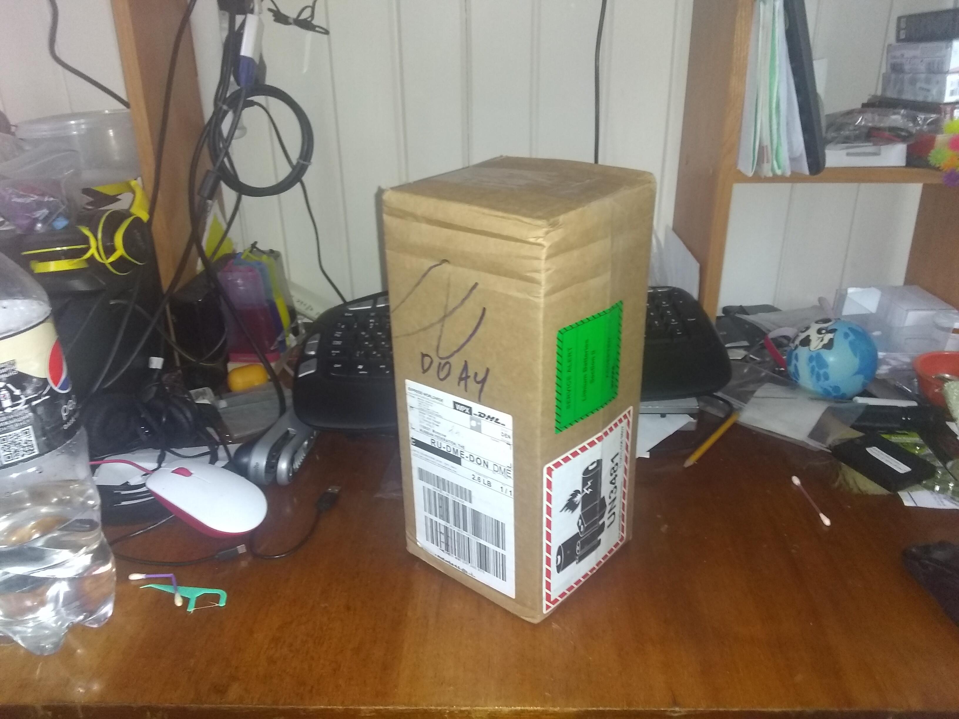
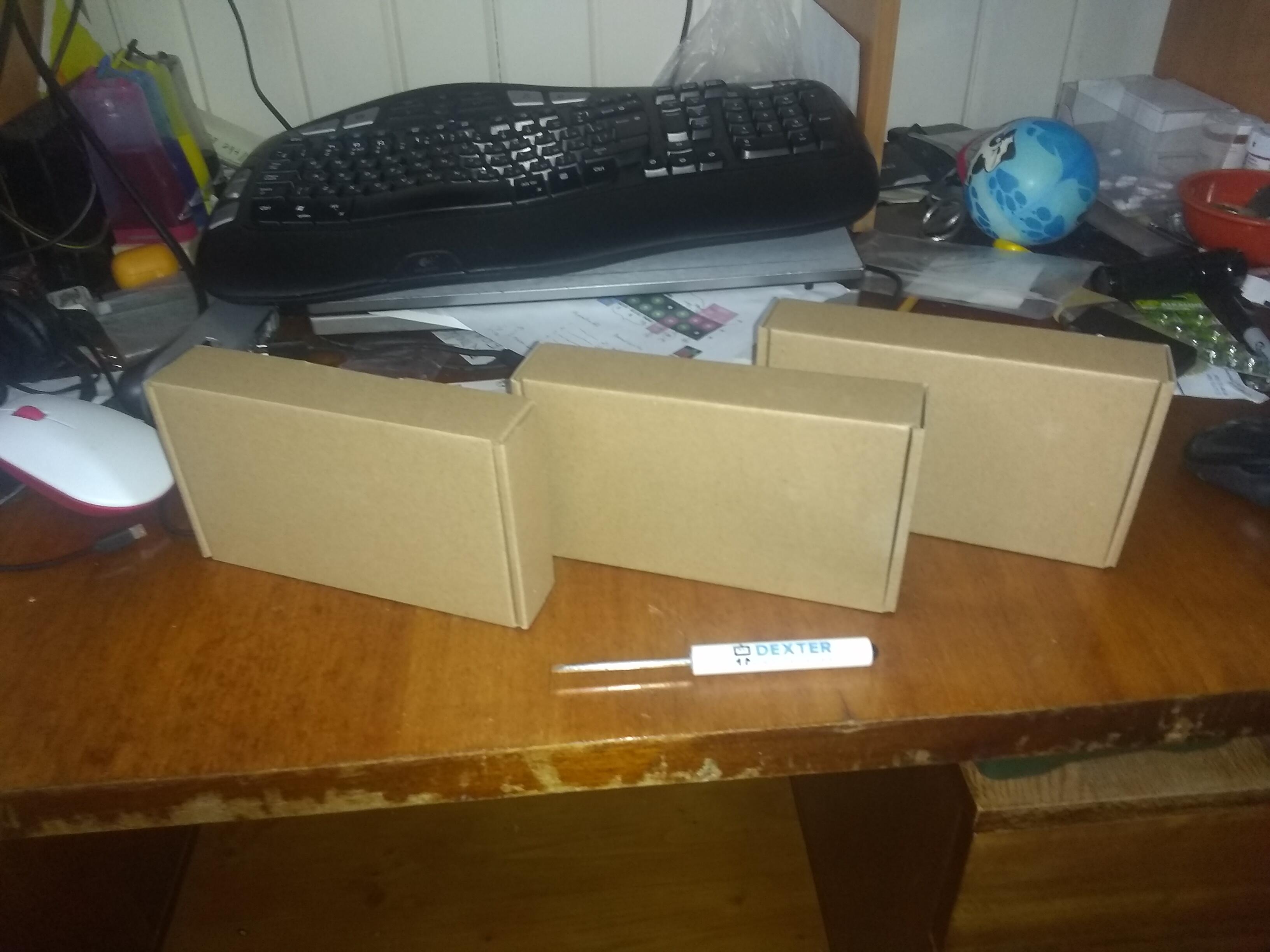
First of all, the batteries were received in good condition.


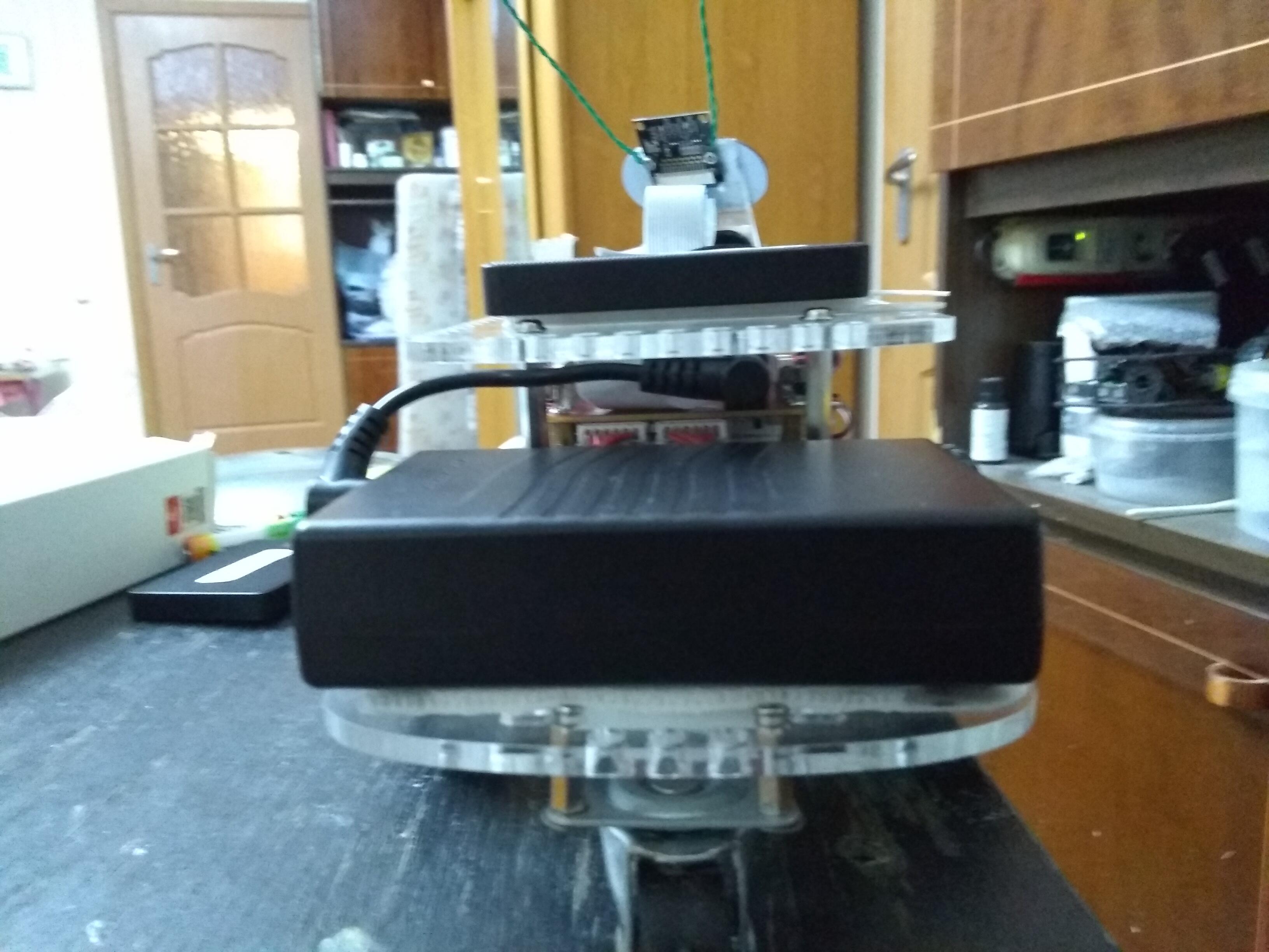
And here is a picture of Charlie with his SSD mounted on his back and the new battery on his back shelf.


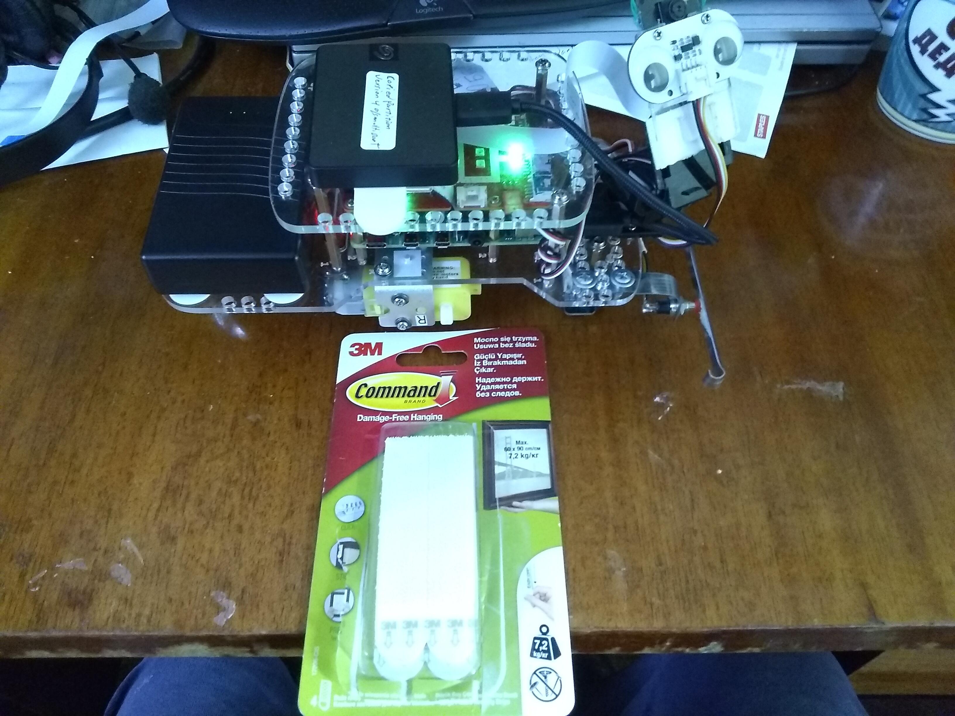
The “Command” strips are how I attach things that I want to be removable.  They have a fierce “Velcro-like” fastener on one side and a semi-permanent foam-tape adhesive on the other.

Comments about the batteries:

What I liked about them:

  1. Assuming that the specs as published by Modular Robotics are reasonably close to accurate, (I have not yet tested their run time myself), they should last a while.
  • With a rated six-hour charge cycle, these batteries recover from a “fully discharged” state about twice as quickly as a set of NiMH batteries which have a “from fully discharged” charging cycle of between 12 to 14 hours.
    • If you don’t have a 12v adapter you can attach the robot to when doing development or testing, having a couple of extras will ensure you always have a fully charged battery available.
  • They already beat the pants off of the NiMH batteries I was using as the batteries hold a charge much longer than the AA size NiMH batteries I have.
  • Note that the AA batteries I have are not necessarily bleeding edge chemistry like the Panasonic batteries are, but they were a lot less expensive too. . .
     
  1. They have an on-off switch.


  • This is especially important as the GoPiGo-3’s controller board draws power even when “turned off”.  This prevents the 'bot from draining your batteries when not in use.  Previously I had to physically un-plug the batteries to prevent them from draining.
     
  1. They have a built-in “power meter”.


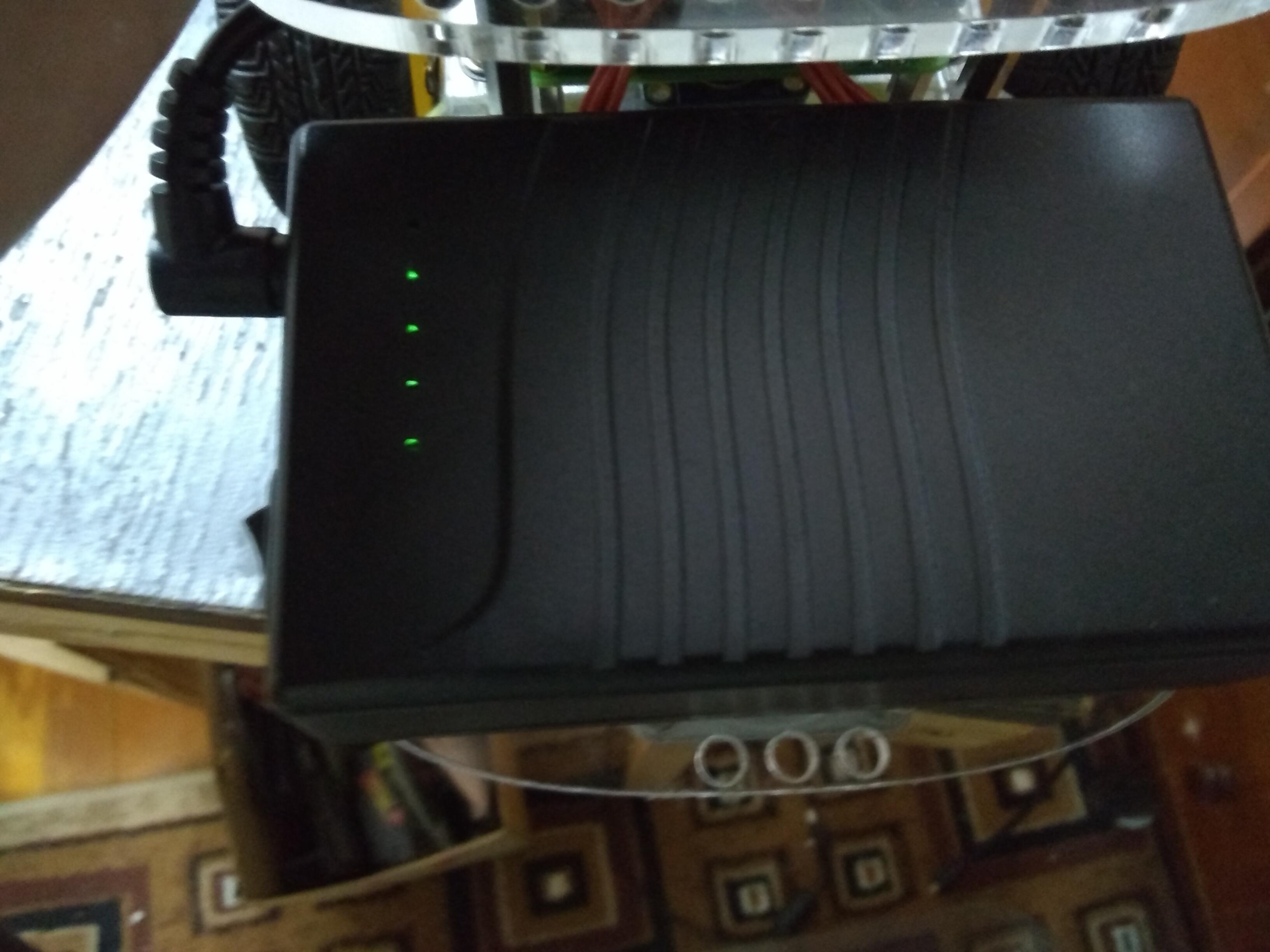
  • This is also very handy as you can get a relative degree-of-charge indication.
  • There are five lights lit when it’s fully charged, but I’ve used this one for a while, so it’s down to merely “four” lights.  My old NiMH batteries would be begging for mercy by now. :wink:
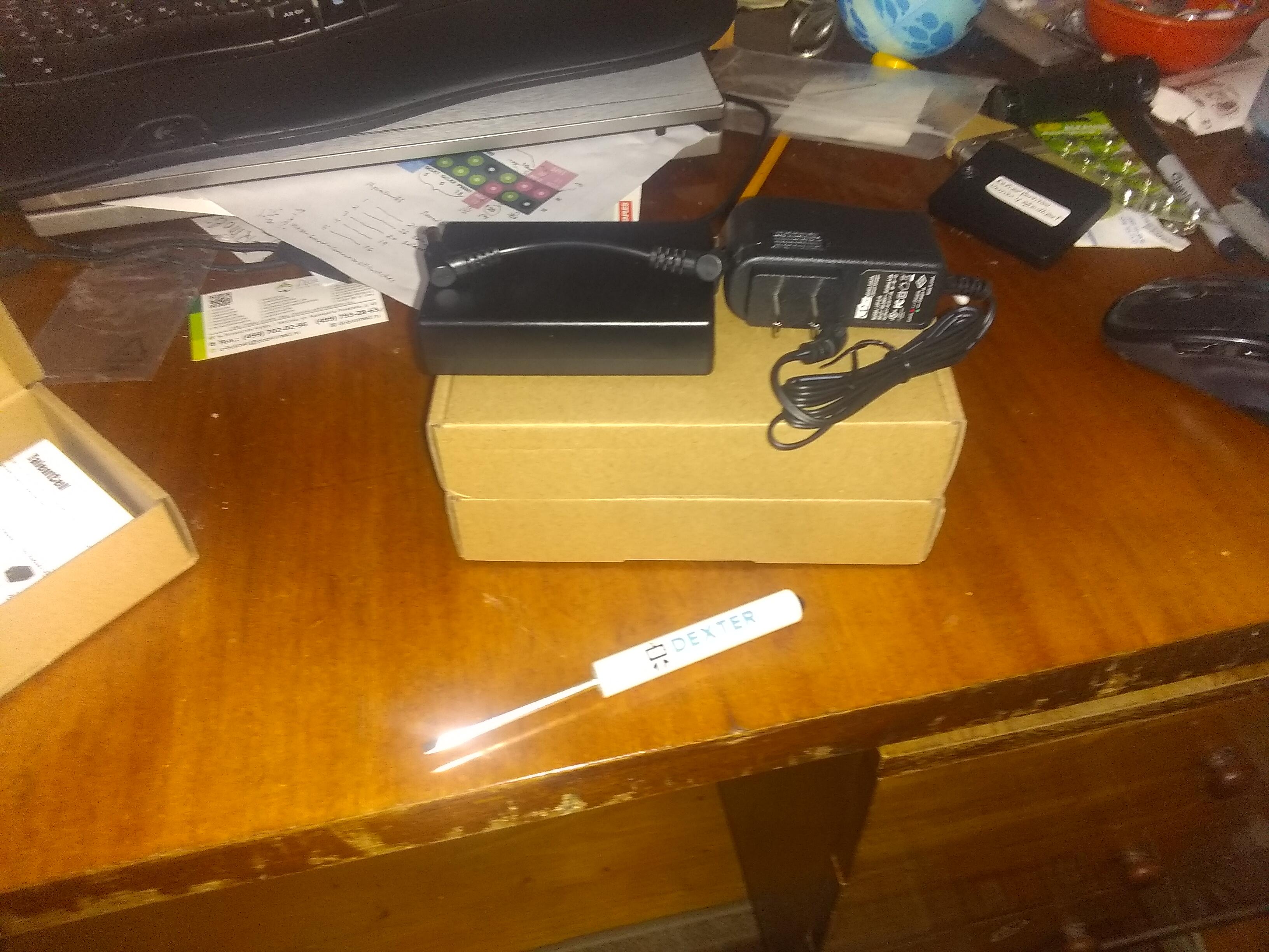
  1. The power-brick that is provided for charging is included with the battery, which is unusual as many battery manufacturers sell the charger as a separate item.
     
  2. The power-brick is a universal power adapter, working equally well on either 110v or 220v mains power.  This means you can take your robot, batteries, and charger wherever you may want to go.  The only down-side is that the mains power plug is a permanently attached North-American, (blade type), power plug so users in places other than North-America will need a mains power plug adapter.
     

Things I didn’t like:

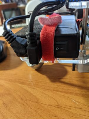
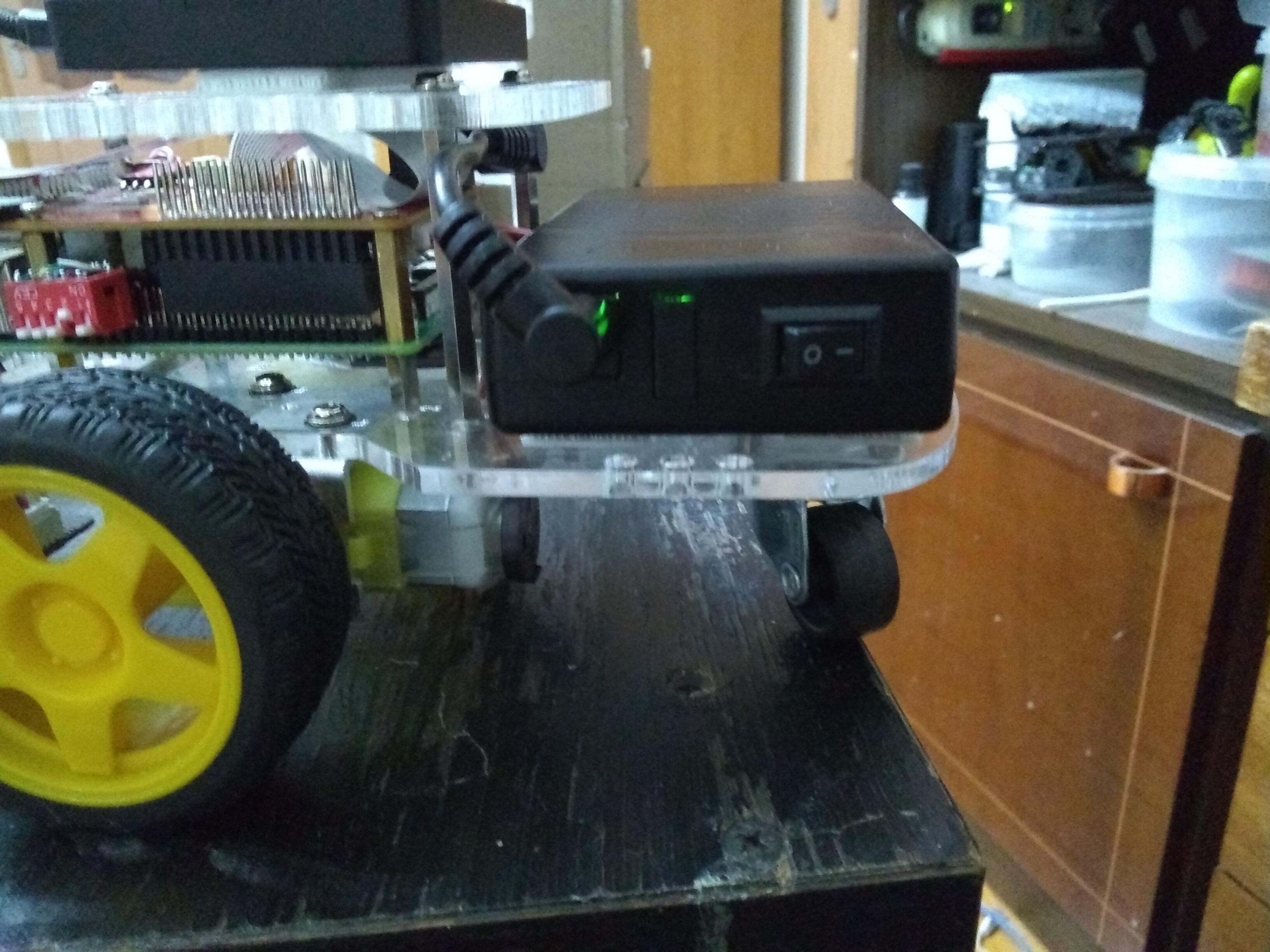
  1. First and foremost - the power cord is too short.


  • Here you can see that it barely, just barely, reaches from the side of the battery to the power connector.
  • If I try facing the battery “the other way around”, the mounting post for the top acrylic panel prevents the plug from being inserted.
  • If the design of your robot is such that you want the batteries on the top instead of the back, the cord won’t reach.
  • Placing the battery as shown, the cord just barely reaches the side of the battery.  You actually have to both pull and twist to get the cord attached unless you remove the battery first.  This places strain on the power connector cord that worries me.
     
  1. The cord is a right-angle cord at both ends.
  • The GoPiGo’s power connector is a non-trivial distance from the edge of the connector, which complicates things when using this cord.
    • The original power cord was a relatively long barrel connector with the cord coming directly out the back.  This made the cord and connector easy to grasp and remove even with the connector considerably behind the edge of the acrylic.
    • The cord for the new battery, with the right angle connector, is extremely difficult to remove because it sits so far back behind the acrylic edge.  (As in “removing the Pi’s SD card” difficult.)
    • I actually expect to have to use a tool to remove the power connector when I decide to plug Charlie into “ground power” for extended development sessions.
  • The right angle connector itself creates problems because it interferes with the stand-off post next to the power connector unless faced to the left.
     

3. There are no charging instructions for the battery as received.

Update:
A closer inspection, (in better light!), of both the instructions and the label on the bottom of the battery contain clear instructions for charging the battery and how the various indicators indicate end-of-charge.
 

Annoyances:
(Things that would have been nice, but aren’t a reason not to get the battery.)

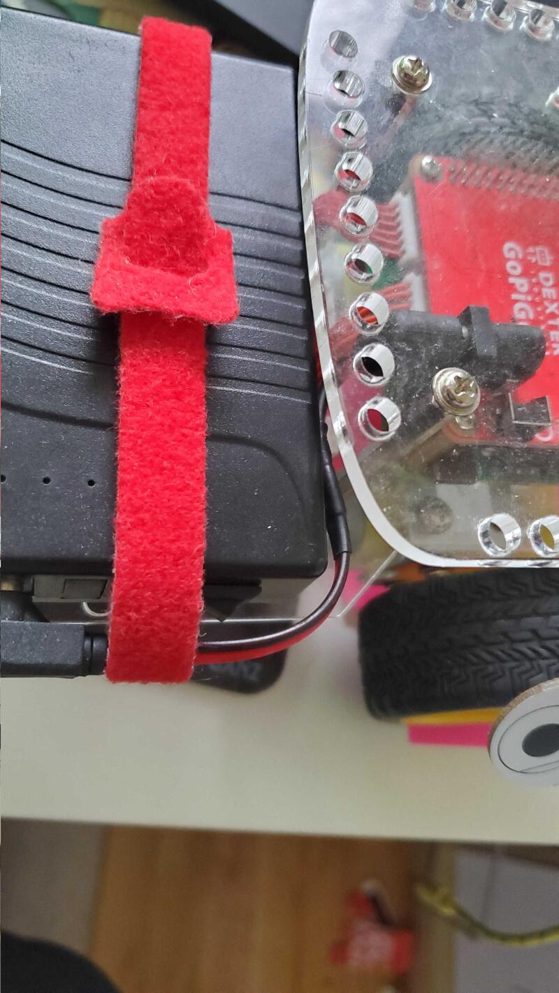
  1. The battery is not the same size and shape as the original 8-cell AA battery pack.  Depending on how you attach it, it either prevents you from using the Velcro battery strap, or it sticks way out past the end of the robot.
  • I don’t know if the newer versions of the GoPiGo will have a different way of attaching the battery or not.  I ended up using sticky Velcro strips on both the chassis and the bottom of the battery to hold it in place.
  1. The battery is lighter than the original battery pack.  Depending on how you have your 'bot configured, and where the 'bot’s center of gravity is, it may have a tendency to tip forward.
  • In my own case, and in the more typical configurations, the robot is still rear-heavy enough to not tip forward when standing or coming to a rapid stop.  However, the change in weight is something that should be noted and accounted for.
  1. The battery is much wider than the original 8-cell battery pack.  This prevents you from using the mounting holes on the sides or back edge of the rear of the 'bot for anything without sliding the battery pack a significant distance to the side.
     
  2. The batteries come with a North American power plug, though the adapter is 110/220v rated. The absence of other power mains plug configurations makes this battery more difficult to use in places other than North America.
  • In Europe, I am using it with a blade-to-pin-plug adapter, which is doable but inconvenient.
     

Overall impression:
The idea of a long-life rechargeable battery pack is an excellent one, especially for classroom or serious hobby use, as the original battery arrangement was woefully inadequate without super-premium cells which are a significant expense.  Based on the limited experience I have had with it so far, I expect it to considerably outlast the original NiMH cells I had in the original 8-cell battery holder, both in run-time and useful life expectancy.

If I were buying the GoPiGo robot for classroom use, I would seriously recommend using this battery both for the extended run-time and the rapid recharge cycle time.

Unfortunately, this excellent idea is considerably diminished by the extremely short power cord which prevents you from choosing alternate battery mounting configurations based on design or need.  (The previous battery pack had a long enough cord to allow several alternate positions and configurations.)  Likewise, the fact that the battery cord’s connector that fits into the GoPiGo controller board is both short and a right-angle makes it virtually impossible to use without tools.

This is partially mitigated by the fact that the barrel connector is a standard size often used for 12v adapters and the advanced user can either modify the existing cord or fabricate a custom one of their own using off-the-shelf parts.
 

Recommendations:

  1. Make the power cord at least 50% longer.
  2. Make the one end that plugs into the GoPiGo controller board a straight barrel connector instead of the right-angle connector currently there.  Note that the end that plugs into the battery is a right-angle connector and should remain so.
  3. If you plan, or desire, to sell these battery packs to places outside of North America, they should have either different power adapter versions, or replaceable mains plugs for the adapter itself, to correspond with the various power receptacles in different countries/regions.
    4. Make sure adequate charging instructions are included with the battery set.
  4. (Nice to have)  Include the “Y” charging adapter with the battery so that the battery pack can be charged without removing it from the 'bot.
     

What say ye?

2 Likes

Note update to article and addition of “Executive Summary”.

Good overall review. Although I really only agree with recommendation #1 :slight_smile:

I had bought the same model (at least something very similar) from Amazon before Modular Robotics carried it, so mine didn’t come with a power cord. From your pictures the one included does look short. The cord I got is quite a bit longer - I had to gather it in and zip tie it. But I think if yours were longer, your recommendation #2 would go away. I almost never unplug the end that goes into the robot, so really no reason for it to stick out. Same for #5 - I just unplug the adapter to charge it. If the cable is long enough there’s enough slack that’s not a big deal. The Y-jack that came with my power cell had straight jacks on both ends, so I wouldn’t have wanted to use it anyway. If it had right angle jacks then it might work OK (edit - see below. I think this would be really handy if it had right angle jacks). As for recommendation #4 - I don’t recall that mine came with instructions. Better that these chargers be intuitive - plug it in, it’s done when all the lights are green. Most people aren’t necessarily follow complicated instructions anyway. As for #3 - it would be nice, but it becomes a logistics headache to stock all possible plugs. Maybe having a low cost adapter available as a purchase option would be an alternative. I guess if they had enough sales to a given market (e.g. the EU) it would be worth stocking different chargers.

Attachment of the battery to the robot can be an issue - I use a long velcro strap I had already. It just fits between the USB jack and the switch, and uses existing slits in the base plate. I wish I could snug it up a bit tighter, but it works OK.
PXL_20210429_174112644

One thing to note - when mine is plugged in to charge, the USB port provides power even if the switch is in the off position. I have my lidar plugged in to the USB - it’s not really an issue in my case, but if someone is using the USB power-out for something else it could be. At the very least it may be slowing down how quickly the battery charges.

/K

2 Likes

Nice rebuttal.

I agree that many of the things I said, and recommendations I made may be considered by some as “WAAAA! Cry me a river!” complaints.  But I just reported on how I perceived the things when I tried to use them.

One thing I did notice on the first battery pack I used - it went down to three dots on the power meter and then - died.  No yellow or red power indication.  No battery warning from the Pi.  Nothing to indicate that I was on the verge of disaster - green light one second, totally dead the next.

When I plugged it back in to recharge, it came back up with three dots lit.

I would have expected it to go to at least one dot before crashing and giving some kind of indication of the imminent loss of power.

Have you noticed anything like that?  How does your pack handle end-of-charge for you?

1 Like

I didn’t take them as “Cry me a river complaints” - I just didn’t necessarily agree. Especially since I think a number of them stem from the really short cord - I agree with that one completely. I wish mine was shorter, but not that short. I think your estimate of 50% longer would be a sweet spot. The charger plug issue I don’t so much disagree as understand why they don’t offer multiple options.

Actually as I’ve thought more about it - a Y-cable with right angle jacks at both ends so I could charge w/o unplugging would be really handy. And as I think even more about it- that would also help mitigate the need for a lot of slack, since once in place you wouldn’t need to unplug the cable very often.

As for the battery - I’ve been working through some online tutorials for ROS navigation, so I haven’t been actually running Finmark very much. But yes, I do recall that was a problem. This was also noted by none other than @cleoqc in this post:
https://forum.dexterindustries.com/t/hands-on-ros-chapter-9/7790/21?u=keithw

Agree completely that it’s an issue. But dare I say it’s “Working as documented” :rofl: :rofl: :rofl:

/K

1 Like

This is the big problem with written replies - you can’t see my tongue planted firmly in my cheek!

I was not trying to say that YOU considered them “cry me a river” complaints, rather that they might be considered, (by people reading this for the first time), as “cry me a river” complaints - and yes, depending on the application they may be more or less applicable.

I also raised, (via a PM), the very real issue of a fire hazard with the original battery holder.  I actually had a small fire caused by an inadvertent short-circuit to one of the exposed contacts.

Compared to the very real risk of a fire caused by exposed contacts on the 8-cell carrier, (which I covered with black electrical tape), a “short cord” is the least of my worries.

Neither do I want to give anyone the impression that I am not extremely grateful for the batteries they sent - I expect them to be a Godsend.

However, robotics can be a fussy science, especially with regard to the physical configuration of the 'bot, so I wanted to place everything out on the table so that people could make intelligent assessments and choices.

1 Like

Yeah, those kinds of battery holders can be problematic. I’ve also tried to cover them somehow if there’s a chance for a short.

It is a problem. Although emoji’s can be overdone, they can be helpful sometimes.

/K

1 Like

Thanks @jimrh for your review. I am glad the batteries have been received are appreciated!

As for the short cable, it is short for a reason. In the classroom little fingers get caught everywhere and pulling the cable or playing with dangling cables is just too attractive - whether on purpose or not. 10 year olds fidget.

So we got the shortest cable we could get, believe it or not!
And this is the recommended (at least for the classroom) installation:

The connector to the red board is vertical. The wire is stuck in the velcro, thus minimising accidental power offs which would corrupt the SD card.

3 Likes

Really great point @cleoqc - I know I get so wrapped up in my particular use cases that I forget the target market is actually education. That does change the design thinking quite a bit.
/K

1 Like

Then something has to be done about the battery’s power indicator.

I have only tried one of the three I received, but when that one dropped to three dots on the power meter - indicating about half of the battery’s charge remaining - it suddenly shut-down without warning.  Upon recharge, it started at three dots.

One second it was a happy bunny, the next - dead as a doorknob.  No low-power indication on the GoPiGo, no low-power icon, no blinking power dots, absolutely no warning whatsoever.  And this is troubling.

Especially in a school environment where the kids may have a tendency to “trust” the power-remaining indication, this could present a problem.  If you’re worried about a “fidgety” 10 year old unplugging the battery by mistake, I’d be even more worried about a battery’s power meter that lies to you and allows the battery to die without warning.

Is this normal behavior for the battery?  Does the battery need to be “trained” through several charge-discharge cycles for the battery meter to be trustworthy?

I totally agree. Those LEDs are sooo misleading, but it’s due to this particular chemistry. The discharge cycle is such that the battery is very good for a long time, until it’s not. There’s no slow degradation for the LEDs to work.

We are debating asking the manufacturer to remove the LEDs but so far we haven’t made that move.

2 Likes

I was rapidly coming to the conclusion myself that the discharge curve was a “square wave”, so to speak.  Just like Wile E. Coyote, everything’s just peachy until you hit the edge of the cliff. . .

I would have thought that, by now, lithium battery makers would have discovered some way to predict end-of-cycle and/or remaining life reasonably accurately.

Update:

I’m seriously considering taking the case off of one of the batteries to see how the manufacturer implements discharge monitoring, what IC’s they use, (if any), and determine if the accuracy can be improved.

Since they advertise overcharge, undercharge, and short-circuit protection, they’re probably using a battery-monitoring-system IC, similar to solutions offered by Maxim.  (This one is an integrated battery state monitor IC that can indicate a reasonably accurate state-of-charge.)  See below, they’re actually using a much less expensive L6033 lithium battery charge controller IC.

If the manufacturer is using any reasonable kind of battery protection circuitry, there should be a way to get a reasonably accurate battery state-of-charge indication better than “five, four, three, dead”.

This is something you need to discuss with the manufacturer - accurate state-of-charge is not an unreasonable request, especially on a battery like this which is going to be used in a classroom environment as it is essential for the instructor to have a reasonable understanding of the battery’s state-of-charge.

What you really don’t want are teachers starting a class with what appear to be well charged batteries and having them die half-way through the session.  If that’s the case, you might as well go back to high-quality NiMH batteries in an 8-cell pack again.  At least there the state-of-charge is more easily determined by the output voltage.

OK people, here’s the deal:

First, the battery module is divided into two major subsections:

  1. Three batteries and a charge controller board as a module.

  2. An “output” module that takes the battery’s power via two big wires and provides an on/off switch, a barrel jack, a five-LED “state-of-charge” voltmeter, and an optional USB connection.

The Battery Module:

  1. The battery module is based on the Chinese manufactured L6033 lithium battery charge controller chip and a pair of 6630 power MOS-FET transistors connected back-to-back to provide the charge/discharge switching.

  2. It appears the battery module manufacturer lifted their circuit right out of the manufacturer’s “reference circuit” on the datasheet.

Viz.:


The “Output interface” Module:

  1. Aside from the on-off switch and a few other things, the output interface module is a 5-LED voltmeter based on the very generic LM-339 quad op-amp/comparator and a resistor divider network.

  2. The problem with using such a generic “voltmeter” circuit in this application is that the voltage swing between fully charged and fully discharged, (assuming you don’t over-discharge the batteries), is extremely small - on the order of a volt or two.
     
    This graph shows the discharge curve of a single Li-Ion battery - a mere half a volt from full to empty!  (Ignore the dotted line, that’s obsolete technology.)

final2a
 
Three cells taken together would have a 1.5v drop from full to empty - 12v when full to 10.5v when empty.

  1. Though the LM-339 can be used quite effectively as a battery voltage monitor, (that’s even one of the standard reference circuits for the device), the difference between the “fully charged” voltage and the voltage considered “fully discharged” should be larger than one or two volts, or special adaptations to the circuit need to be provided.
2 Likes

I would suggest against it until you have a better way of indicating state-of-charge.

What I would do is mention that - on this battery - the top three LED’s indicate “Full” - “Half” - “Empty” and that when you get down to the third LED indicator, you’re riding the ragged edge of disaster.

There are probably better ways to use that circuitry more accurately, but I’ll have to do some research on that one.
 

Update after some additional research and thought overnight:

One thing that CAN be done is to restore the software voltmeter and maybe even update the firmware to provide a “lithium” option that will handle power management to at least some degree via the power LED on the GoPiGo PCB.  If the power LED’s on the battery are totally bogus, having at least SOME power-left indication via the power LED on the GoPiGo is better than nothing.

If I get the chance, I will take one of the output modules, carefully measure the voltages at the various LED points, find a copy of its reference circuit, and propose modifications that would cause a better and more linear scale.

1 Like

Wow - quite the investigation. The voltage/charge curve is really interesting.
The way I have mine mounted I can’t really see the LED’s anyway. So far it’s not an issue - I’ve just run short tests.

As I run it longer I’ll look into writing a voltage monitoring routine, maybe with a shutdown if it gets too low.

Maybe the short term solution is tell teachers just to put tape over the last 2 LEDs as a reminder to just use the first three as you suggest.

/K

1 Like

Like I’ve said before:  Maybe my software skills aren’t so great, but I’ll always put money on my hardware skills.

In this case it wasn’t too difficult once I removed the four screws holding the case together.  They tried to hide the part number for the charge-controller IC, but they didn’t try too hard - a few drops of 647 solvent, (which I suspect is a mixture of Xylene and Toluene - also known as model airplane glue), and the black paint came right off.  Once I had the numbers for the two primary IC’s, the rest was history.

Unfortunately, the charge controller IC is only manufactured in China, and appears only to be sold to Chinese manufacturers, (there were no, repeat zero, non-Chinese sources of these products), so:

  • Finding the relevant documentation was not that easy - I was just about to VPN into a Chinese end-point to help my search.

  • The only non-Chinese reference to this part was a Russian IC look-up site that provided a link to a vendor I had already examined.

  • Once I found it, all the documentation, (including the data-sheet), was in Chinese and most sites required a subscription to enter.  The fact that I found anything appears to be shear luck.
     

This is one of those situations where Chrome shines with its automagic translation of foreign language web sites and such.

Like programming, if you have any serious experience with hardware design and reading datasheets, you can pick out the relevant information even if “it’s in Chinese” - which it was this time, literally!

1 Like

That might be a bit of a challenge, depending on the absolute accuracy of the voltage monitor on the GoPiGo - we’re talking a 1.5v delta here - between bung full and dry as a tumbleweed.

Using NiMH batteries, the total voltage swing was something like 4 volts - 12v to about 8v DC - so the need for insane precision wasn’t necessary.

AFAIK, I would want to take a reasonably precise variable “bench supply”, (and an accurate reference voltmeter), and slowly vary the voltage between 12v and low-voltage cut-off on the GoPiGo-3 repeatedly, to determine the “figure-of-merit” for the precision of the on-board voltmeter.  (@cleoqc, can you comment on this?  Has any research already been done here?)

Once you know what level of precision you can expect, then you will know if it is even possible to write a low-voltage warning/cut-off for the GoPiGo.  In other words, do you have enough accuracy to handle a 1.5v delta with any degree of confidence, and a sufficient number of digits of precision to identify exactly where you are on the voltage curve?

That’s the $64,000 question.

(Now all I need is about $300 to get a decent variable bench supply. . . .)

1 Like

May not be feasible. I’ve used the function call to get the voltage from the GoPiGo-3 board, but I haven’t done any testing on how accurate and stable the readings are. Even if it’s not accurate in an absolute sense, if it’s stable and consistent, it might still be useable.

/K

1 Like

That’s easily done. Run a cron job every 15-30 min to record the voltage. Start from fully charged and keep running until it dies. Examine the log and repeat the test several times - full-charge to dead - and you should see a consistent pattern emerge giving the measured beginning and end voltage.

If you want greater precision at the end-point, you can increase the sample rate once the voltage drops below a certain value.

Yeah - not hard. Just never did it. Now that it’s come up maybe I’ll work on that this weekend.
/K

1 Like