That’s easily done. Run a cron job every 15-30 min to record the voltage. Start from fully charged and keep running until it dies. Examine the log and repeat the test several times - full-charge to dead - and you should see a consistent pattern emerge giving the measured beginning and end voltage.
If you want greater precision at the end-point, you can increase the sample rate once the voltage drops below a certain value.
You might be able to do this for your specific battery but there’s a wide variation between batteries. Mine for example will show the second LED for about 5 min, and the first LED only for oh, 10 seconds? Blink and you miss it.
However my backup battery shows the second LED for less than a minute and then it dies.
It’s the chemistry of this particular battery, you had the right words @jimrh , it’s like a square wave. It’s good, good, good, and dead. That’s also the reason we removed the battery level warning from GoPiGo OS.
We tell teachers to charge up the batteries the day before they plan to run the GoPiGos. Since the batteries are good for hours, they can avoid shutdowns by starting with fully charged batteries.
You are absolutely correct, except it isn’t the battery, (batteries), that are the problem unless they’re totally crappy cells.
The problem is very likely to be the precision of the resistors in the divider network for the battery meter - large tolerances will eat up more of that 1.5v delta and make the variation in readings battery to battery unacceptably broad.
The LM339 is spec’d to have a minimum voltage delta, (input- larger than input+) of 5 mv to trigger the comparator action. Being able to resolve to 0.005 volts is plenty of precision for an accurate fuel gauge covering 1.5 volts.
Assuming the absolute delta for the battery from full to dead is 1.5v, (this should be measured or we should look at the manufacturer’s spec sheet), the LM339 can provide accurate readings so long as the resistor tolerances are not too broad. I would suggest 1% precision resistors to provide the most accurate readings and consistency between devices.
They will need to use precision resistors because the absolute delta voltage between full and dead is vary narrow - unlike a NiMH or NiCad - where wider tolerances don’t matter that much.
What say ye?
Do you think you could talk to the manufacturer about:
Getting a datasheet for the battery module or a set of specifications for that module itself?
Maximum and typical voltage at full charge.
Minimum and typical voltage at fully discharged just prior to shutdown.
Voltage range, (delta), both maximum and typical, over which the battery module will shut-down due to discharge.
re-calibrating the values of the resistors in the network to give the range of readings we need.
Using precision resistors, and a precise voltage reference, to improve the accuracy of the readings.
Let ME see the schematic for the output interface board so I can calculate the values and tolerances for the resisters and voltage references on that board for them to implement. I would not mind “sacrificing” a battery’s output board to become a development board for improving the battery state-of-charge gauge.
This modification would be useful for all the customers of their Lithium-Ion batteries as it would provide a more accurate “fuel gauge” for the battery.
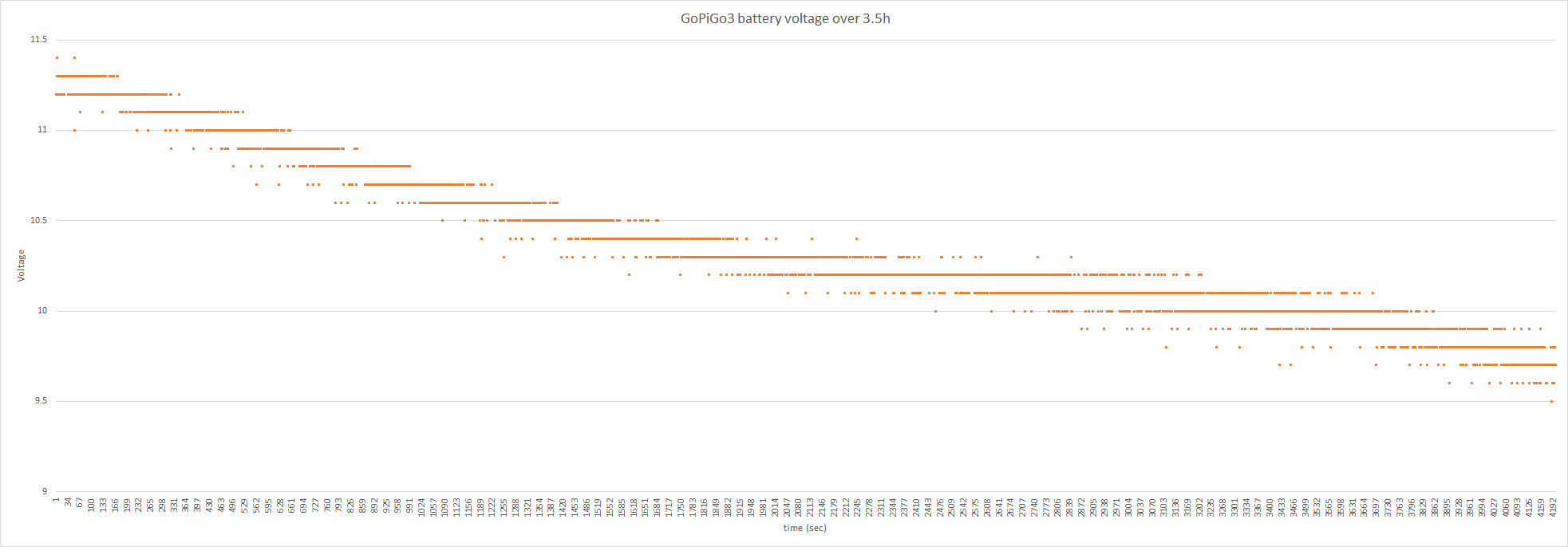
I ran a quick test to see how the GoPiGo3 reads the voltage in ROS. I have a battery pack similar to the one Modular Robotics now offers, with the exception that it also has a USB output, which I use as auxiliary power for the lidar. I ran the motors back and forth with Finmark suspended on a plastic box so the wheels weren’t actually in contact with the ground. But otherwise I ran it with a realistic load - the lidar was running as well as the camera and distance sensor. I captured the voltage (as published to the /battery_voltage ROS topic) every 3 seconds. It ran for 3.5 hours before I got a couple of readings at 9.6 volts (I only printed to the screen every minute just so I wouldn’t have too much on my terminal). I had decided not to let the cells drop much below 3.2 v, so I stopped at that point. The battery itself was still showing 3 lights.
I rounded the voltage to the nearest 10th to avoid unrealistic precision, so the values do appear as discrete steps. It’s clear there is a lot of bounce even so. Mostly only by 0.1 V, but a fair bit by 0.2 V, especially in the latter half of the testing.
I’ll repeat this a couple of times to see if it’s consistent. Based on this I think I could monitor the voltage OK, but I’d have to use a rolling average over a fairly large number of values (I could also cut down on the sampling frequency to make it a little easier). I was thinking I could flash some of the lights at a certain point (and maybe change color as the level got lower). What I’d really like to figure out how to do is run a monitor program that cleanly stops everything at a certain value.
What does the first derivative show?
(I’m not sure how to do calculus on the Pi.)
I wonder what the base frequency of the chatter is. maybe a simple Fourier transform can isolate that and you could filter it out digitally?
I’ve noticed what appears to be battery noise on my 'bot too, but only when the motors are running under load. I notice it as video noise when running the remote camera routine.
Instead of a digital filter, once we know the frequency of the noise, we might be able to filter it at the battery itself.
It doesn’t surprise me that we’re getting noise because the batteries output is “filtered” through a pair of mosfet transistors that are likely chopping up the voltage somewhat due to regulator action by the battery controller IC.
Perhaps a couple of capacitors across the battery pack will help? (A relatively large one to smooth the voltage curve, and a small one to filter high frequency noise.)
There is certainly variability in the reading. Not sure that it’s from the battery per se - as you note it could be from the motor. And not just the wheel motors - I have a motor spinning the lidar as well.
I haven’t done any further analysis. Really I just wanted to understand what data I had available to me from the robot to see if it was feasible to monitor internally. Within ROS I can just get the data from the already published ROS topic without any fuss. I can just use a moving average to do what I need to do - if I average over enough readings any truly aberrant results won’t matter much. And that would be both batter independent and fairly straight forward.
Given that the topic is published by whoever wrote the ROS drivers indicates they were expecting folks to want to monitor the battery voltage. Makes sense that this need would be anticipated, given that the GoPiGo3 board has a way to monitor voltage included.
Apologies to @jimrh for OT reply - broke it out separate for discussion
I need to figure out a “Safety Shutdown Measurement” for this new battery pack.
On Carl, the measured actual battery voltage is always 0.6v more than the GoPiGo3 reported measurement, so a GoPiGo3 reading of 9.6v may be 10.2v at the battery or 3.4v per cell. (The 0.6v is from the reverse polarity protection diode.)
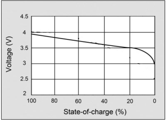
The TalentCell pamphlet lists the Output as 12.6 - 9 volts, and @jimrh’s chart shows 9v (3v per cell) as totally discharged.
I’m thinking of using a shutdown limit of 3.25v per cell, 9.75v at the battery for a GoPiGo3 reading of 9.1v which should correspond with discharging to 10% capacity.
The bot should probably be in a “minimum load” configuration at the knee 10.5v / 9.9v on GoPiGo3, so that a servo swing or commanding the driving wheels do not drag the voltage down artificially.
Sounds reasonable - I didn’t think to check the actual output voltage - I should do that and compare it to the readings I get from Finmark. Does the Talent pamphlet specifically say it cuts out at 9v? That’s still a bit lower than I’d feel comfortable going, but it would be nice to know it does have an internal cut-off.
/K
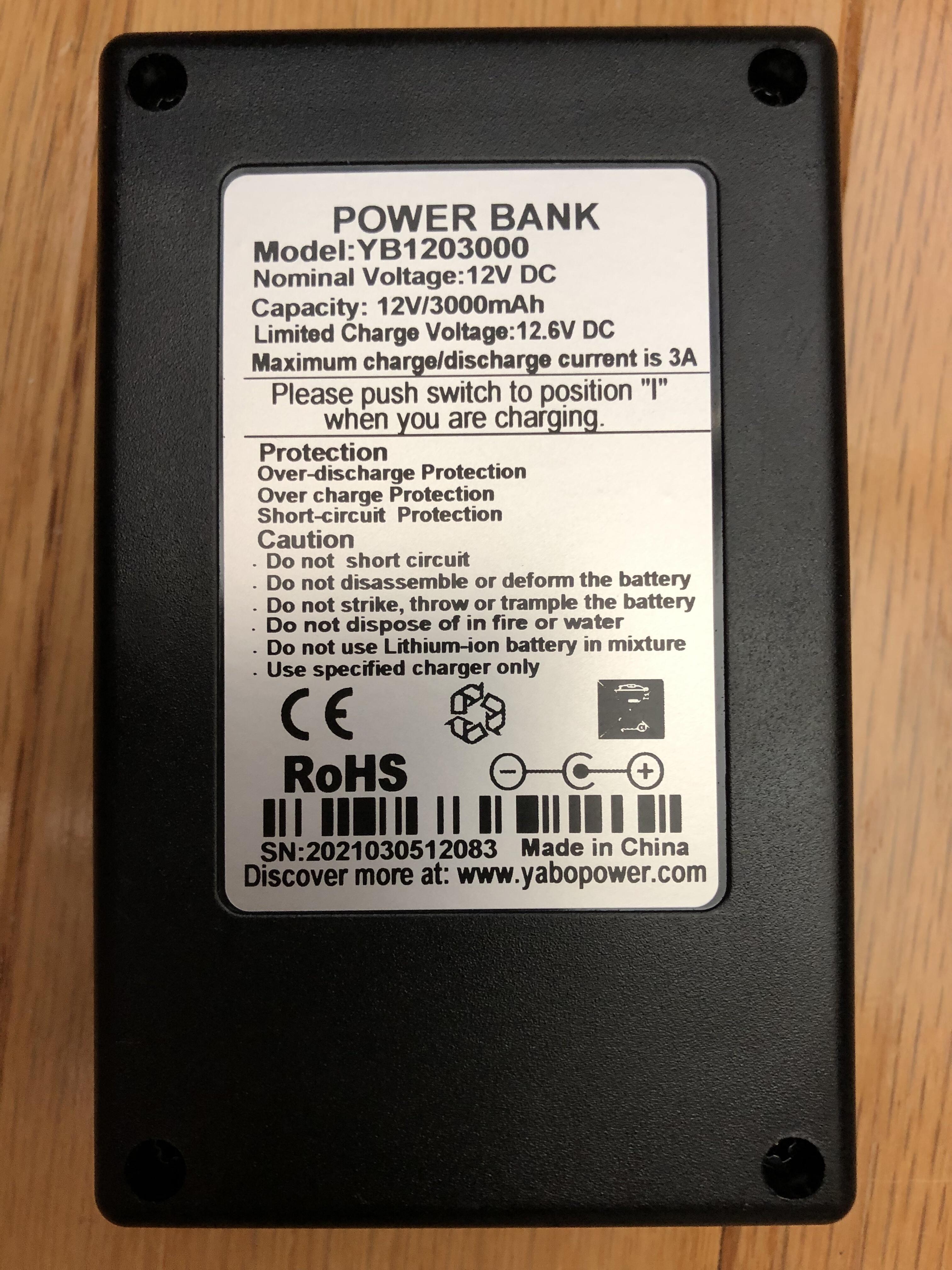
That is what I was expecting, since the little product spec says
| Spec. of charger | 12.6V 0.5A |
|   Charge Time    |  ~6hrs     |
BUT, I’m charging (from fully discharged to protection cutoff) with the kit charger right now, and the inline meter says 11.5v 0.955A which I would guess will end up at 3.5-4 hours to green if there is any tapering. I just checked the adapter and indeed it says 12.6v 1A output.
(Also interesting - charging current is cut in half if the battery pack’s power switch is in the off position. The product pamphlet says to charge with the switch in the ‘1’ position.)
Good to know - I’ve been charging mine in the “O” position.
@cyclicalobsessive I’m sure you’ll notice, but for the USB model, if you charge with the lidar plugged in to the USB, power will be going to the lidar (this is true whether the switch is on or off). But the off switch does cut power to the USB when it’s not charging.
And I left the robot overnight with the switch on by accident - the Raspberry Pi was powered down, but the lidar was still being powered. I was able to charge, so the battery must have cut itself off at some point. I didn’t think to measure the charge before I recharged.
I don’t know how to edit pictures like that to eliminate the irrelevant data, (at least without butchering it), so I flagged it instead of not showing what was, IMHO, a useful graph.