Hands on ROS: Chapter 9

“Integrating with the remote PC”
If you copy over the ydlidar files from the book (as suggested on P290), then the git clone steps on P291 won’t work (you’ll get an error because there’s already a folder named ydlidar). In order to have the latest files I removed the book copy and did the git clone step. May not have been the best move as we’ll see…

For some reason in “Running the YDLIDAR ROS Package” I did not see “/tf” when I ran rqt_graph. But I did confirm (with “rostopic list”) that the /tf topic was being published (and could “rostopic echo” just fine).

if you use the “git clone” approach, then you won’t immediately be able to do the next step - there is no display_scan.launch file. There seem to be 3 files in the book’s files that aren’t in the git version of the ydlidar folder:

  • src/scan.py
  • launch/display_scan.launch
  • launch/gopigo3_ydlidar.launch

You’ll want to copy them over. You won’t actually need to catkin_make again, but doesn’t hurt to be sure.

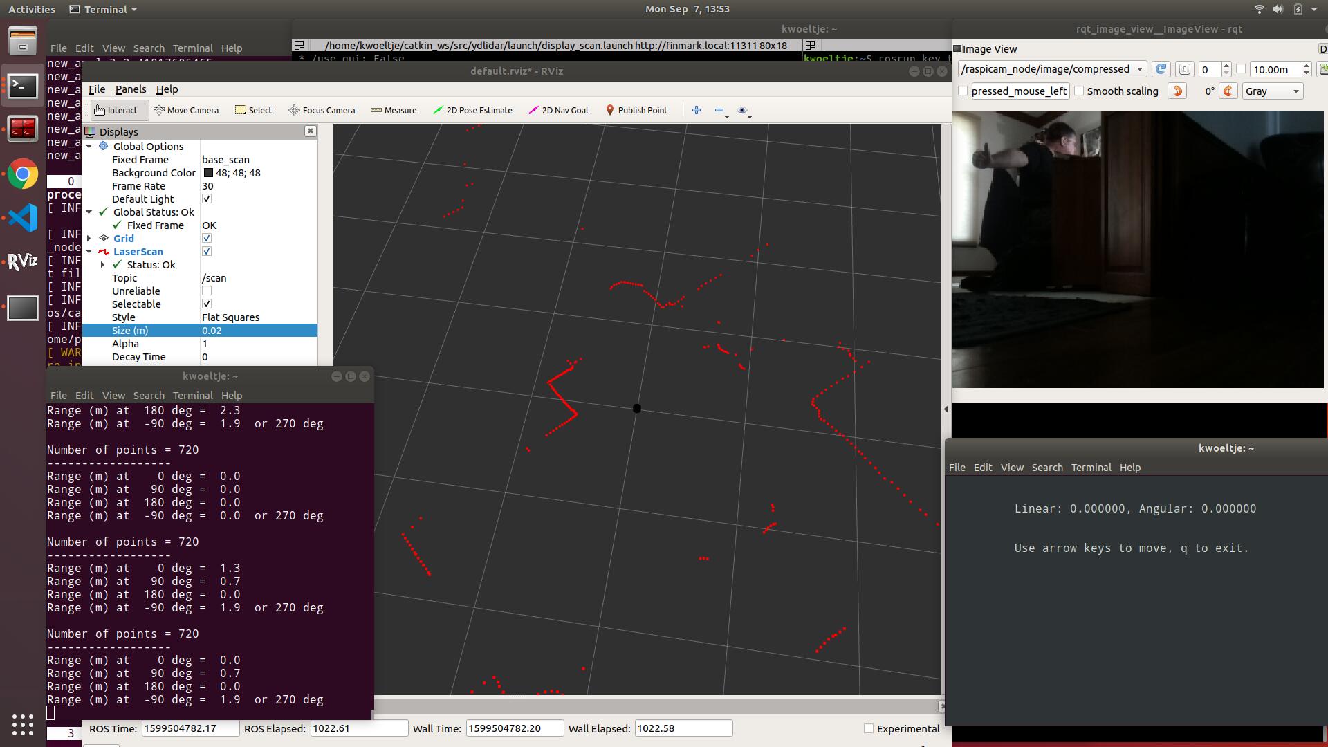
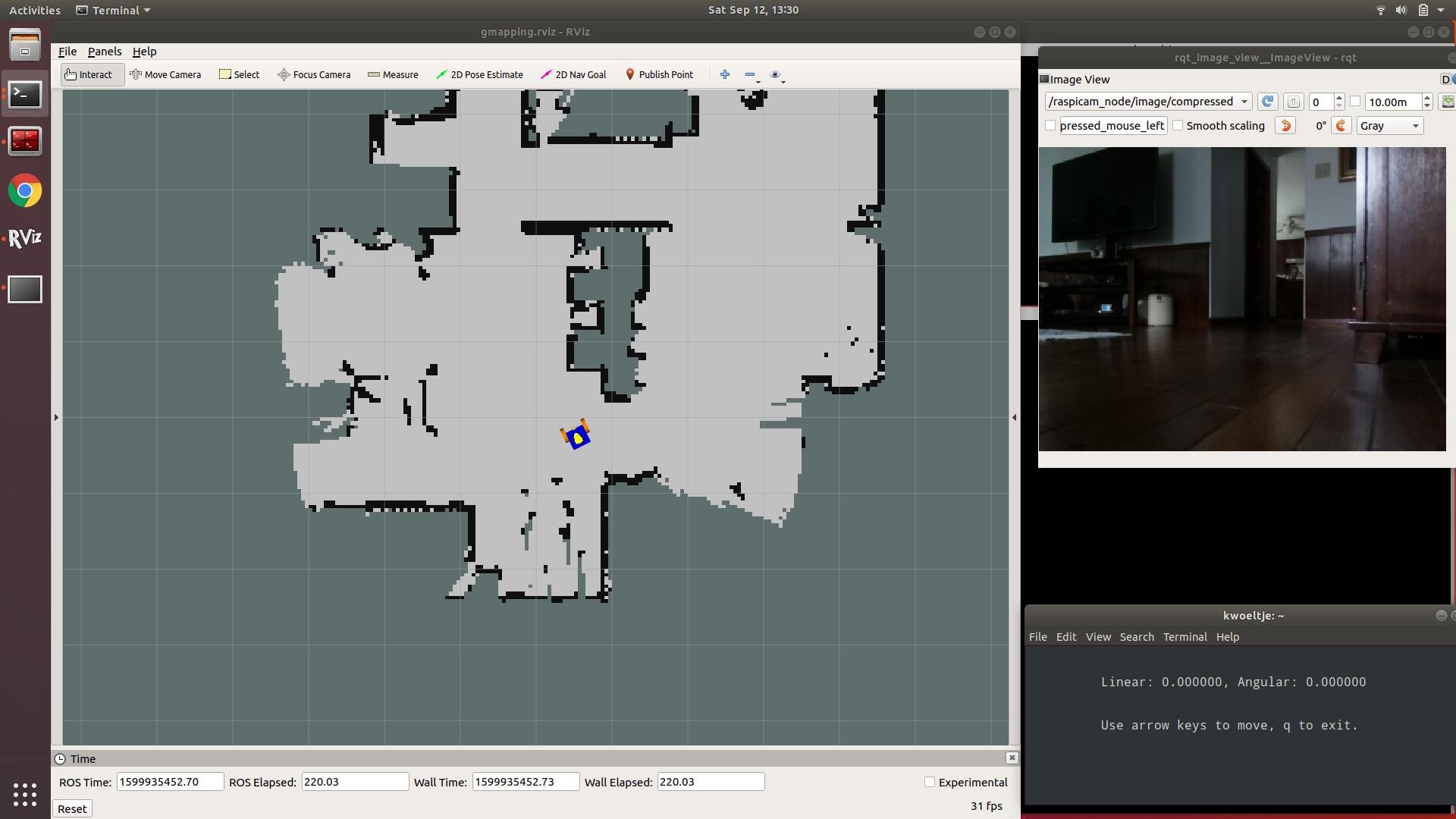
When I launched display_scan.launch I did not see any scan, and had an error stating "Fixed Frame [map] does not exist. Turns out this was easy to fix (but took a few minutes of panicked googling):

  • Under “Global Options” click on “map” next to “Fixed Frame”; choose “laser_frame” from the drop down
  • Towards the bottom of the window, click the “Add” button
  • About 2/3 down on the list that pops up (in the “By display type” tab) you should see “LaserScan”; pick that and click the “OK” button
  • Click on the small triangle to show the options under “LaserScan”
  • Click the empty column to the right of “Topic” and then select “/scan” from the dropdown.

You should now see the lidar point cloud. If you increase the “decay time” for the display (e.g. to 2), you’ll have better definition, but delayed reaction to movement.

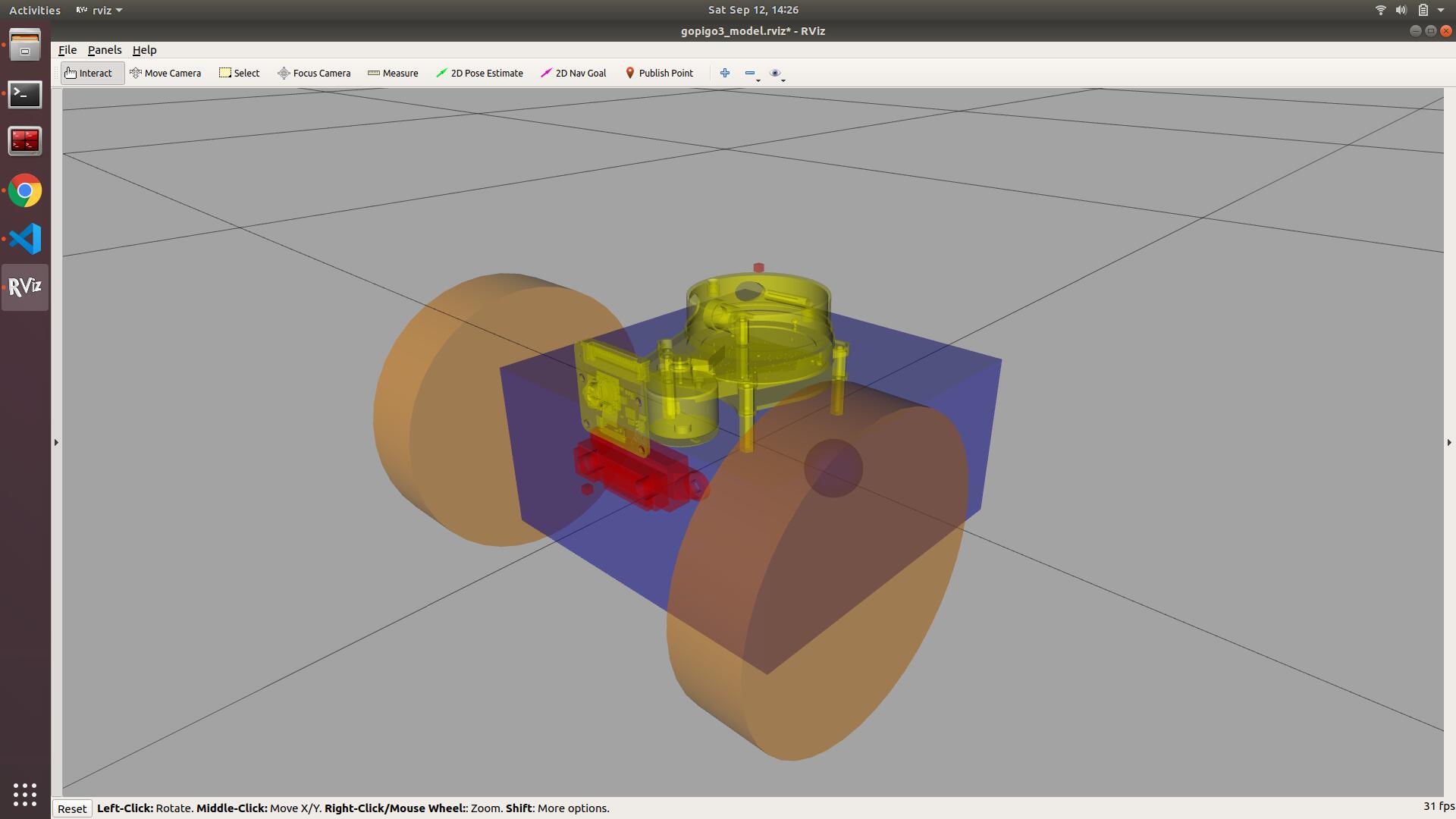
Oh - also note you’ll have to add the robot model manually as well if you want that.

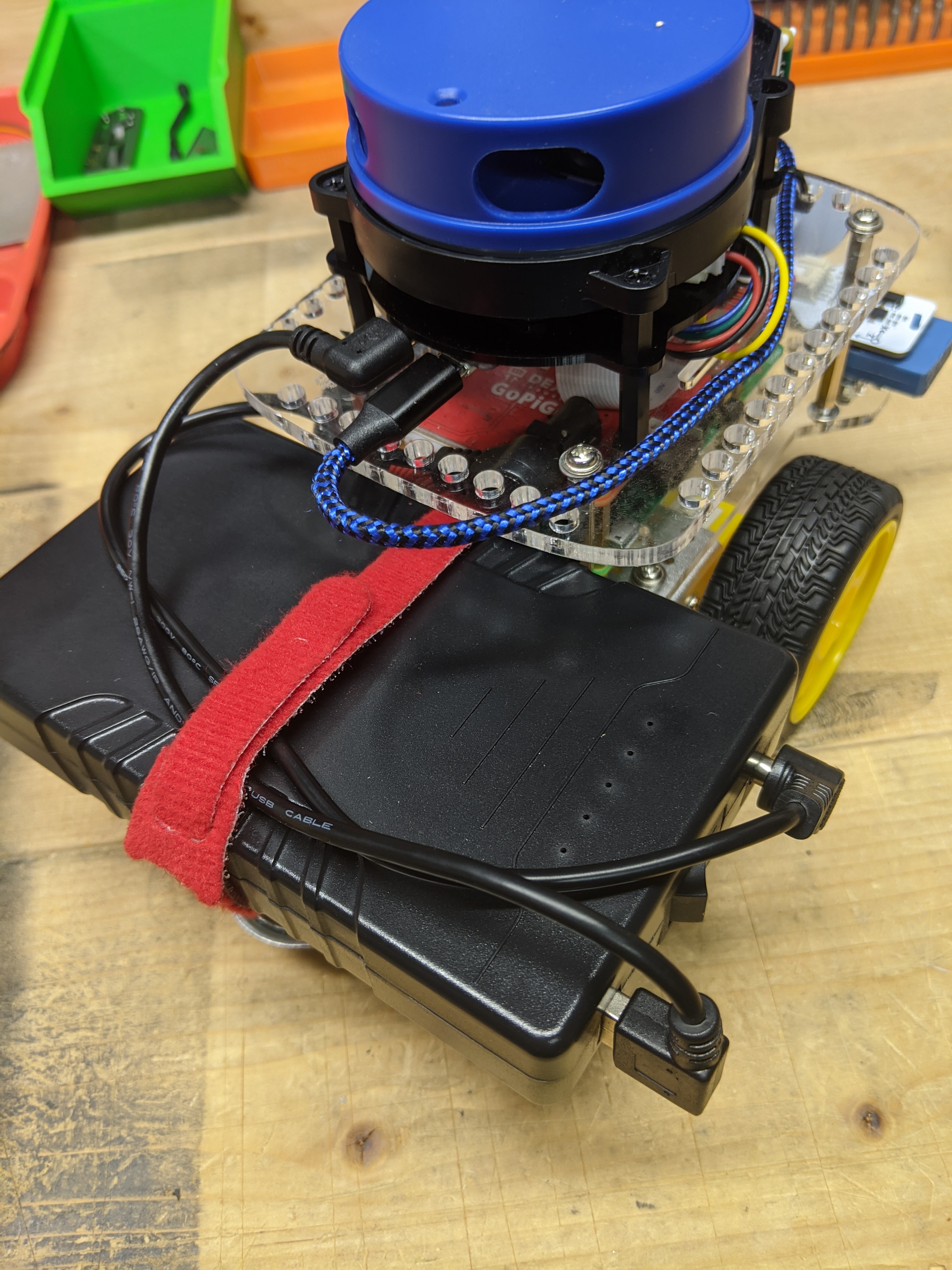
OK - next steps - “Integrating with Raspberry Pi”

/K

2 Likes

Despite what the book indicates, the YDLIDAR wouldn’t spin when connected to the robot even though it ran just fine connected to my laptop. This is the exact same problem that @pitosalas described in this forum post: YDLIDAR and gopigo3.
I did try just running a second USB cable from the Raspberry Pi to the micro-USB power input, but that didn’t do it either. Ended up using a small USB power bank that I got as a freebie at an event, designed to recharge cell phones. Seems to work fine - should be OK for now.
I’ve ordered parts to make what I hope will be a better long-term solution for providing power to the “power” input.
/K

2 Likes

“Integrating with Raspberry Pi”
You’ll want to copy over the launch/gopigo3_ydlidar.launch file from the book files after you clone the git repository (the other extra files in the book are run on the laptop, as noted in a previous post). Test to make sure the lidar works (see note about power supplies above).

Since I’m not running a desktop on the robot, I skipped the section on “Visualizing scan data in the Raspberry Pi Desktop”

For grouping files, not sure why the author didn’t do an “include” for launching the lidar. Be that as it may, the file is already written and available in the book files. One thing I added after the first <include…> line was:

<include file="$(find raspicam_node)/launch/camerav2_410x308_30fps.launch" />

That way I could run rqt_image_view on my laptop to see via the camera.

“Visualizing scan data from the remote laptop”
When I tried to launch “display.launch” as suggested on P300, it would always kill my lidar. In looking at the file it seems that it’s launching another ydlidar_node. I tried commenting that out whole section out by modifying the first and last lines:

<!--node name="ydlidar_node"  pkg="ydlidar"  type="ydlidar_node" output="screen"> 
 ...
  </node -->

This actually worked, or you can continue to use “display_scan.launch”. You’ll have to tweak RVIZ as noted previously (and the robot model doesn’t actually show up automatically unlike the book suggests on p301.

I found that scan.py gave very mixed results in terms of distances. Since I had mounted my lidar looking forward, I didn’t have to worry about my axis being off by 90 degrees.

When everything was running I could operate the robot with key_teleop, get a point cloud with the lidar, and see what was going on via the camera (had to resize the different windows to get it all viewable on the laptop). If you look closely you’ll see I’m giving a big thumbs-up.
/K

3 Likes

Pretty neat, and quite a feat you have achieved!

(Not sure what planet that “wall time” is for…)

1 Like

indeed, the LIDAR needs its own power source. The Pi is unable to supply enough power for it.
You’ve made it through the hardest part !
(Eventually, the top acrylic will have holes for the LIDAR. I need to find some time to calculate where they will go)

2 Likes

Me neither - never really paid much attention to it. I’ll have to look it up. /K

2 Likes

Pre-drilled holes would be handy - some folks might not have the equipment to drill their own (or might not be willing to risk ruining their top plate).

A power splitter/adapter would also be a neat accessory. So that I didn’t have to deal with two power sources, I ordered a voltage regulator (from Amazon) that had a USB output. Unfortunately I paid more attention to the size (looking for something that could mount easily, and got one with a mini-USB adapter, not the micro. The good news is that this forced me to just go ahead and sacrifice a micro-USB cable and make things the right length.


I had a female barrel-jack plug adapter with screw terminals (like this from Sparkfun). I sacrificed a 9V battery adapter for the male plug. I just twisted together the positive and negative leads for the male plug and unput to the USB voltage adapter (after stripping the wires of course) and then screwed them down in the female adapter. Use some shrink tubing to keep things tidy.
For the USB output I used a couple of solder shrink sleeves that I had to connect the wires, then again shrink tubing to keep things tidy.
I had also gotten in some shorter micro-USB cables to tidy things up. Overall I’m happy with the results, and it seems to work fine.


Now I just have one jack to deal with. I do have to remember to unplug the jack after the system is powered down, since the “power” input on the lidar will draw power if a USB source is plugged in, so the batteries would drain. This set up also makes it easier to plug in a 12V wall adapter for when I’m testing at my desk (always on a stand so there is no unexpected movement).
/K

2 Likes

Navigation
With the lidar working it was on to the navigation section of the chapter. Here my decision to mount the lidar facing forward really bit me. When I ran the gopigo3_slam.launch file, it was clear that the map being generated was sideways to the robot, which was causing a lot of confusion. There hadn’t seemed to be a problem when I generated the point cloud (in the image above) - which was clearly generating a map based on the lidar pointing forward.

So - first step was to modify the urdf file. For this chapter it’s “gopigo3_actual.gazebo” in the gopigo3_navigation folder. I decided that since I was making changes, I’d go ahead and reposition the camera and distance sensor to be a bit closer to reality. I’ve attached my modified file for reference. That looked great when I ran gopigo3_rviz.launch:

Unfortunately, when I launched the slam file, it still showed the lidar pointing sideways. After a lot of confusion (and triple checking my URDF models and the slam launch files), I looked more closely at gopigo3_ydlidar.launch. In that file there is a specific transform being done with a reference to base_link and base_scan. In re-looking at the URDF file, only the laser distance sensor (i.e. the lidar) had a reference to base_scan. So I tried changing that:

    <node pkg="tf" type="static_transform_publisher" name="base_link_to_base_scan"
        args="-0.03 0.01 0.15  0.0 0.0 0.0   /base_link /base_scan 40" />
        <!-- original args="-0.03 0.01 0.15  -1.6 0.0 0.0   /base_link /base_scan 40"-->

That actually worked. I need to do the ROS tf tutorials to figure out exactly why it worked. But for now I’ll take it. For anyone who goes this route of mounting the lidar facing forward, I’ve attached the modified launch file as well.

I was able to generate a map:


.
Note that on p310 your laptop user may not be “ubuntu”, so the map file portion of the command should be:

map_file:=/home/<your_user_name>/catkin_ws/test_map.yaml

With that done, I was able to navigate atomously by setting nav goals:

If you look really closely, you can see that the little yellow lidar model is facing forward now on the model.

So after a little hardware update and some URDF and tf trouble shooting, I have an actual working autonomous robot!!

/K

modified_gopigo3_actual.gazebo.txt (12.2 KB) modified_gopigo3_ydlidar.launch.txt (1.4 KB)

2 Likes

@KeithW, could you summarize the autonomous behavior? What elements run onboard the bot versus off-board? (perhaps there is a graphic in the book - I have not purchased the book yet)

Up till now you were “driving”/commanding from the laptop keyboard, the bot was scanning, and the laptop was calculating localization and logging the path, correct?

At this point it is a “random wander, avoid obstacles, and build map” that runs on your laptop?

1 Like

OK, saying I have an “autonomous robot” is being a bit generous since it’s not really all on the robot. But I was excited.
Roscore is running on the robot, along with the lidar.
The actual navigation stack, AMCL, is being run on my laptop. You’re correct - earlier I had generated a map by driving the robot with my keyboard. AMCL now uses that map. In RVIZ you can set a navigation goal, and then the robot will navigate autonomously to that point - the local and global cost maps are run on the laptop.
It all worked fantastic earlier today when I first ran it. Unfortunately I’ve just tried it again and the robot kept getting confused about its actual position. So more work to be done.
/K

1 Like

We have started recommending this particular battery to people who use ROS and a LIDAR.
https://www.amazon.com/Talentcell-Rechargeable-6000mAh-Battery-Portable/dp/B00MF70BPU/

It can power both the robot and the lidar together, with no soldering involved.

2 Likes

Certainly looks like a tidier solution. The model you linked to doesn’t have a USB output. They have a similar model that does:
https://www.amazon.com/TalentCell-Rechargeable-3000mAh-Lithium-External/dp/B00ME3ZH7C/?th=1
I think you’d need that to power the lidar, but maybe I’m missing something.
I like that it has an on/off switch as well.
/K

1 Like

I was copy/pasting from my phone and picked the wrong one on Amazon. Glad to see you found the one with the USB port.

2 Likes

@cleoqc did you mean to link this one?

1 Like

The 3000mAh and the 6000mAh will both work. The 6000 one will last longer of course, but the 3000mAh is a better fit on the back of the GoPiGo.
Either one will resolve the issue of powering both the Pi and the LIDAR.
Btw, thanks go to @pitosalas for letting us know about this option.

Cleo

2 Likes

I think that’s actually the same one that I linked to - it’s not apparent from the URL because both the 3Ah and the 6Ah batteries are on the same page. How did you get the bigger link? That’s certainly more helpful.
/K

2 Likes

There was a summary at the bottom of the page comparing all the different models, with a link that worked. Prior I kept trying to choose the 6000mAh version and copy the URL, but it kept giving me a link to the 3000 version - totally weird how javascript works I guess.

1 Like

Word of advice: if you choose to go with this battery, do not trust the LEDs. They stay at 3 over 5 forever, and you have about 10min when it drops to 2 LEDs, and about a min, sometimes less when you hit one LED.
Very misleading.
But apart from that, great battery!

3 Likes

I couldn’t quite visualize it when I ordered the battery, so I’ve taken a picture of what it looks like on the robot. It stick’s out ~3/8" past the back deck. I got a couple of right-angle connectors to minimize how much was sticking out on the right side.
/K

1 Like

@KeithW it will be interesting to know how ROS deals with turning uncertainty. I did a lot of turn accuracy and turn repeatability testing with batteries on the back deck and batteries closer to the virtual axle center, as well as max acceleration without lifting the castor or flat out tipping onto the nose.

(Also found the Pololu delrin ball castor to be greatly superior to the stock metal castor.)

Having the batteries just behind the virtual axle resulted in very good turn accuracy and repeatability (especially if all turns are made in the same clock direction). Placing the weight over the castor causes floor surface irregularities, such as floor board cracks or tile grout, to have a greater influence on turn accuracy and repeatability.

If ROS does some Kalman filtering with the encoders and IMU, perhaps it will not be as sensitive to battery placement.

2 Likes