IMU-seless at ROS

Sorry - couldn’t resist the bad pun.

I’ve been exploring using the DI IMU with ROS. There is a ROS driver (IMU-sensor.py). The weird thing is that the driver publishes its own transform between “world” and “IMU”. This transform seems to override the transform between the IMU and base_link that is generated by the robot_state_publisher based on the URDF. At first I thought this was a frame naming issue, but it didn’t matter if I called it “imu_link” (as suggested by REP 145) in the URDF, and named the frames that way in the ROS driver, or if I kept “IMU” in the driver and changed my link name in the URDF. Regardless - if I wasn’t running the IMU driver I had my transform between the IMU and base_link, and if I was running the driver that would disappear, and instead there was a transform between the IMU and “world”

The other thing I noticed is that the axes were all backwards. Just sitting flat I get:

linear_acceleration: 
    x: 0.09 
    y: 0.06 
    z: 9.72

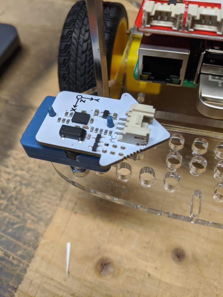
But since Z is supposed to be point up, I expected gravity to show about -9.8 on the z-axis. If I tilt the robot forward I expect positive X acceleration, but I get negative. Likewise if I tilt the robot left, that should be positive y-axis acceleration, but I get negative. As a refresher, the mount looks like:


I could tweak the driver, but that’s a bummer. Not sure why this is. I didn’t try to see if the magnetometer data was similarly backwards.

I may come back to messing with this, but I’m somewhat dissuaded because I keep getting errors: grove_i2c_transfer error: Timeout waiting for data. If I’m just running the imu alone, I have no issues. But if I’m running the lidar, etc, I get this regularly and have to relaunch the IMU. So for some reason the driver just can’t keep up.

Getting back to the first paragraph - I thought about commenting out the lines the publish the transform between “IMU” and “world” (making sure first that I’m using the same name consistently (either “IMU” or “imu_link”) for both the URDF and the driver and seeing what things look like. But since the driver keeps crashing, trying to figure out the IMU just doesn’t seem like a productive avenue. I’ve decided that this was a somewhat educational, but ultimately non-productive detour in improving my localization. Maybe I’ll come back to it later, but for now I’ll get back to working on other optimizations.

/K

2 Likes

Maybe you could try disabling the IMU to see if that improves things?

2 Likes

That’s what I"m doing - running it w/o launching the IMU.
/K

2 Likes

Good idea for the moment at least. I completely rewrote the IMU drivers for Carl, and I expect to have to do the same for ROSbot Dave.

It sounds like the ROS node doesn’t reconfigure the axes from the DI driver’s assumed:

# on GPG3 we ask that the IMU be at the back of the robot, facing outward [, pointed up]
1 Like

It looks to me that that node code is a total BJ (Bernardo Japon).

It could be that changing the frames to match the gopigo3_node’s odometry publishing might work to allow choosing between {odom, imu_link} in Rviz - (but I’m really extrapolating from my limited understanding here):

Change:
transform = TransformStamped(header=Header(stamp=rospy.Time.now(), frame_id="world"), child_frame_id="IMU")

to:
transform = TransformStamped(header=Header(stamp=rospy.Time.now(), frame_id="imu_link"), child_frame_id="base_link")

but, and this is a really BIG BUT - BJ’s code is based on the DI IMU “non-Easy” interface code, which is not mutex protected. I believe that is the reason you are seeing the I2C errors.

But even the DI EasyIMUSensor() class didn’t protect everything, so I had to add (and more):

 - imu.safe_axis_remap()                  remap axis for actual chip orientation (default GoPiGo3)
 - imu.my_safe_calibrate()                uses the NDOF SYS value instead of just mags value
 - imu.my_safe_sgam_calibration_status()  returns all four cal status: sys, gyro, accels, mags
 - imu.safe_read_gyroscope()              returns the gyroscope values x, y, z
 - imu.safe_read_accelerometer()          returns the accels values x, y, z
 - imu.safe_read_linear_acceleration()    returns the linear accel values x, y, z
 - imu.safe_read_temperature()            returns the chip temp degC

AND even my more protected IMU still caused really nasty I2C errors once a month or so (that only a cold boot could fix).

There may be a better way to interface the IMU included in this article (with the IMU plugged into I2C1 or 2 rather than AD1, but perhaps it would then be incompatible with DI’s Distance Sensor I2C usage.)

Integration always finds issues that unit testing cannot. IMO, DI was not trying to support a “full up” robot using every possible combination of their sensors. We are forging more new ground than just ROS-ifying the GoPiGo3. Even BJ did not put it all together, it would seem.

1 Like

I thought about that - but as I read about the IMU it’s outputs are supposed to be relative to the outside environment, so I think that’s why the transform is written the way it is. It may be that that the localization packages that integrate this can somehow handle the linkage. I hadn’t gotten that far. [EDIT] The more I think about this the more I think it will work. I wouldn’t even need to publish the transform - it would come from the URDF. As I noted - it’s probably not necessary now for what I want to do, so I’ll just ignore the IMU for the time being.

Looks like you found the node on GitHub. If I come back to wanting to use the IMU I’ll look at updating the driver - at least that might help the crashing issue.

/K

2 Likes

True, with a significant caveat:

It’s relative to a specific orientation.

The Dexter BalanceBot has the IMU oriented one way.

Carl, and other instances of GoPiGo code, expect a different orientation than the BalanceBot.

Perhaps ROS expects a different orientation - like flipped over and turned around?

AFAIAC, I run the software and adjust the orientation of the IMU to match.

It’s a LOT easier than re-writing the code. :wink:

1 Like

Strange. . . .

I remember you saying something like that to me awhile back. . . :wink:

Military implementations of an IMU are shrouded in secrecy and, (from the very little I’ve heard), getting accurate tracking requires a federally funded effort.

The relatively inexpensive chips we get, with the relatively un-sophisticated code we have, it’s a miracle we get anything at all.

Angst and difficulties seem to be the norm.

1 Like

Reading the ROS documentation it expects either an ENU orientation (the standard: X: East, Y: North, Z: UP); and that is what seems to be marked on the IMU. But the other orientation that occurs is NED (X: North, Y: East, Z: Down). As I write this I’m just now realizing that is exactly how the IMU is configured. There are threads on converting ENU to NED - seems like at least some folks do it at the driver/publisher level.
/K

2 Likes

What prevents you from just flipping the IMU so the axes point in the “correct” direction instead of re-writing the [#$&∆¶π%!!!] publisher?

Seems to me that a “hardware” fix should be much easier to successfully accomplish than trying to turn a blue pig’s ear into a golden brocaded silk purse at the software level - and screwing up God only knows what else later on.

1 Like

If that’s the case, shouldn’t there be a software switch that tells ROS which orientation your IMU is using?

Kinda’ like the dip-switches on the back of an old-time modem, you gotta tell it what to expect if you want to get anywhere at all.

'eh?

P.S.
@cyclicalobsessive,

Do you remember which one the GoPiGo software expects?

1 Like

That should work for the accelerometers, but might then mess up the magnetometer orientation - I’d have to check that.

Would make sense, but I haven’t found it.

No idea since I never played with that much. But I’d imagine it’s written to accommodate the IMU as it is out of the box.

/K

2 Likes

But doesn’t that depend on which way the box is facing when the postman delivers it?
:thinking: :stuck_out_tongue_winking_eye: :man_facepalming:

2 Likes

ROS way: everything is configuable, everything must be configed, including configuring the multiple, simultaneous, synchonous and asynchronous configuration methods. Hardware is fixed and better not change without telling ROS via a configuration change!

2 Likes

Neither, GoPiGo3 “expects” (defaults to) a non-ROS, non-IMU default orientation and the HoR code is putting its own assumptions into the mix.

2 Likes

. . . which explains why I was so confused trying to orient the IMU the first time.

. . . which (also) explains why standards are so important.

It reminds me of a post office poem/advertisement I saw awhile back:

:wink:

2 Likes

I started looking for ROS2 tutorials for SLAM and Nav. They seem a bit incestuous - SLAM says to use Nav to make a map, but the Nav tutorial says it requires a map.

Then I backed up a bit in the table of contents, and the tutorial talked about setting up your odometry AND your imu for fusion by a robot_localization node with a kalman filter that combines the odometry and the imu to publish the tf instead of having the robot node publish it like gopigo3_driver does.

So it looks like I need to modify my gopigo3 node to:

  • (continue to publish the odom topic)
  • if an IMU is found, publish the imu topics (imu,mags,temp, calibration_state?)
  • have a no_tf parameter to disable the tf publishing, or comment out the code?
    and always run robot_localization since it will use what ever it can find - just odom, or odom and imu in this case.

The tutorial seems to suggest that before I start working on Nav and Mapping, I need reliable localization.

You were saying you plan to ignore the IMU for the moment.

Do you think

  1. I should ignore it as well?
  2. or should I work on a reliable, configurable DI IMU node (that does not pub tf anymore)
    (a ROS2 version then I would back port to a ROS version for you to test)?
  3. or should I integrate the IMU into my ROS2 gopigo3 node (and not pub tf anymore)
    (and then back port the idea into a ROS version for you to test)?

I’m leaning toward 2) which doesn’t blow up anything I have running so far, and I can then do 3) once the IMU driver code is solid.

1 Like

Based on the following answers.ros.org post - what you are seeing for Z is correct and your expectation is reversed

If the vehicle is level on the Earth’s surface, the X and Y accelerometers should report about 0 m/sec^2 and the Z axis accel should be approx +9.8 m/sec^2 reflecting an apparent upward acceleration away from gravity force.

Pitching forward is about the Y axis not X, (and it should be positive).
Rolling left is about the X axis not Y, (and it should be positive).

The rate gyros should be in accordance with the right hand rule as stated in REP –103.

Rotation about the Y axis (pitch motion) should be positive in the nose down direction.

Rotation about the X axis (roll motion) should be positive for right side down motion.

Rotation about the Z axis (yaw) should be positive for CCW rotation looking down on the vehicle.

1 Like

They do all seem to be intertwined. And as you noted, you can’t do localization without first having a map. I think I generated a reasonably good map with SLAM - now it’s the ongoing localization that seems problematic. And perhaps I have too high expectations - my roboland may be too small (and hence the tolerances narrow). I thought it would make things easier, but that may not be correct.

That sounds right. But the node still needs to know where the IMU is in relation to the robot, so there still needs to be some tf between base_link and imu_link.

You do good work. My own approach once I start back with the existing node and work from there.
/K

2 Likes

I had seen that post, but I read is as the poster asking whether their assumptions were correct, and I didn’t see a clear answer. However I’ve now read REP-145, which does clearly state:

  • Accelerometers
    • The accelerometers report linear acceleration data expressed in the sensor frame of the device. This data is output from the driver as a 3D vector, representing the specific force acting on the sensor. [emphasis mine]
    • When the device is at rest, the vector will represent the specific force solely due to gravity. I.e. if the body z axis points upwards, its z axis should indicate +g. This data must be in m/s^2.

I had missed that PEP before. I guess I should think of it as the robot accelerating 9.8 m/s upward along the Z-axis to counteract the pull of gravity (otherwise it would be moving toward the center of the earth). Or another way to think of it (perhaps a better way) is that if the robot was in a space capsule that was accelerating at 9.8 m/s along the Z-axis of the robot, the robot would have the exact same reading. In retrospect I’m kicking myself - this is simply Einstein’s principle of equivalence from his general theory of relativity. Who said ROS was complicated :slight_smile:

Right- rotation would be positive. But as noted above I was thinking of gravity as “pulling forward” and so expected positive linear acceleration. But as we’ve established, I didn’t have the right mental framework.

Now that that’s clarified maybe I will go back to messing with the IMU sooner rather than later to tackle the tf issue.

Thank you @cyclicalobsessive for getting me quite literally re-oriented.

/K

2 Likes