I recently purchased the IR receiver and transmitter from Seeed studio [Linked below]
And have been looking for python code in order for the IR receiver to work. I came across an article (linked below) regarding the example code in the github repo using a Keyes Remote. I tried to use the code out of the box, but unfortunately it was not able to pick up any of the signals. Further following the advice, I started to use the instructables link starting with step 8
In the tutorial it mentions to “connect the data pin of IR sensor to Pin-18 of Raspberry Pi.”. I’m unsure as to which pin this is relating to in regards to the GrovePi board
I’m a complete novice at raspberry pi and circuitry, and that has probably contributed to not understanding this response well. I have done some research regarding the ports, and trying to figure out which GPIO ports then corresponds to the GrovePi ports but have not been able to find anything of use. – hence my question:
As adviced, I have the IR receiver plugged in to the RPISER port on the grovepi that is connected to the raspberry pi. Following step 8 in the instructables tutorial, what gpio_in_pin number should i put in to allow it to connect?
Can you confirm us that you had run the installer script for the Grove IR Receiver from our GrovePi repository?
Instructions on how to install the dependencies for the Grove IR Receiver can be found right here at this link:
Okay. I’m going to test it and then reach back at you and give you a feedback about it.
While I’m doing this, are there any screenshots you might share, logs you’ve got, anything that might be of any help for us?
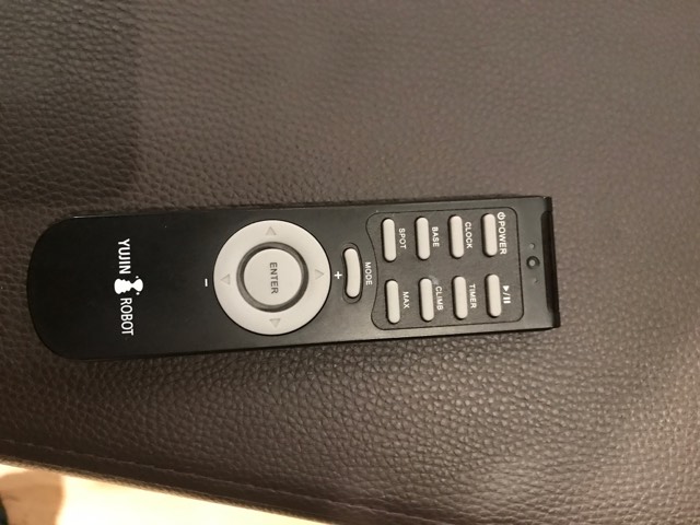
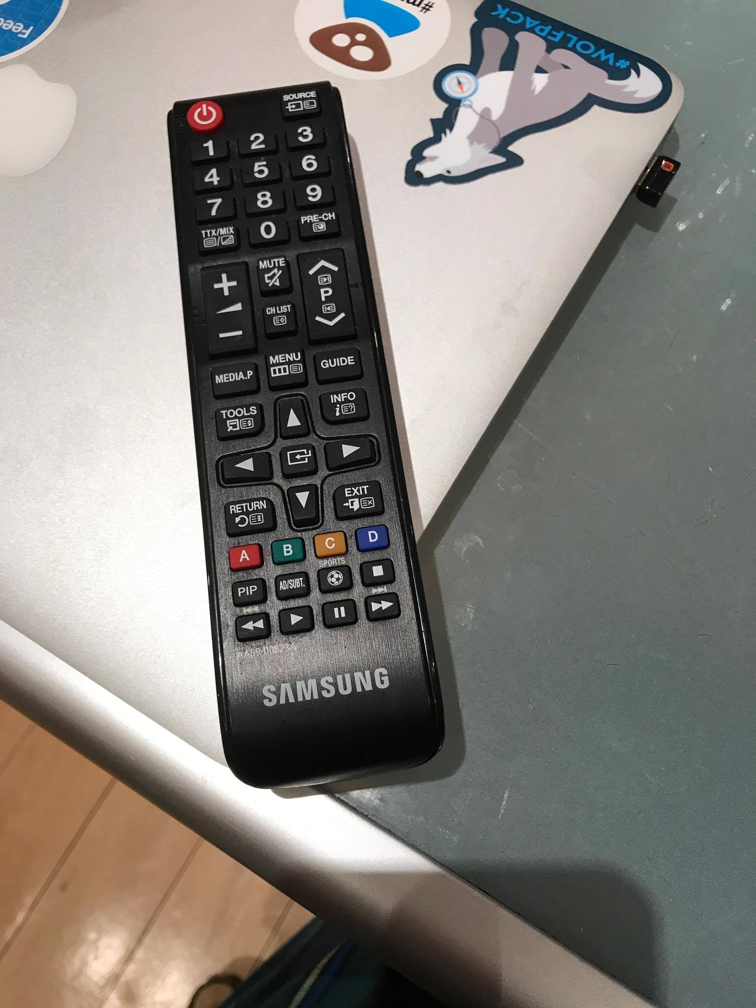
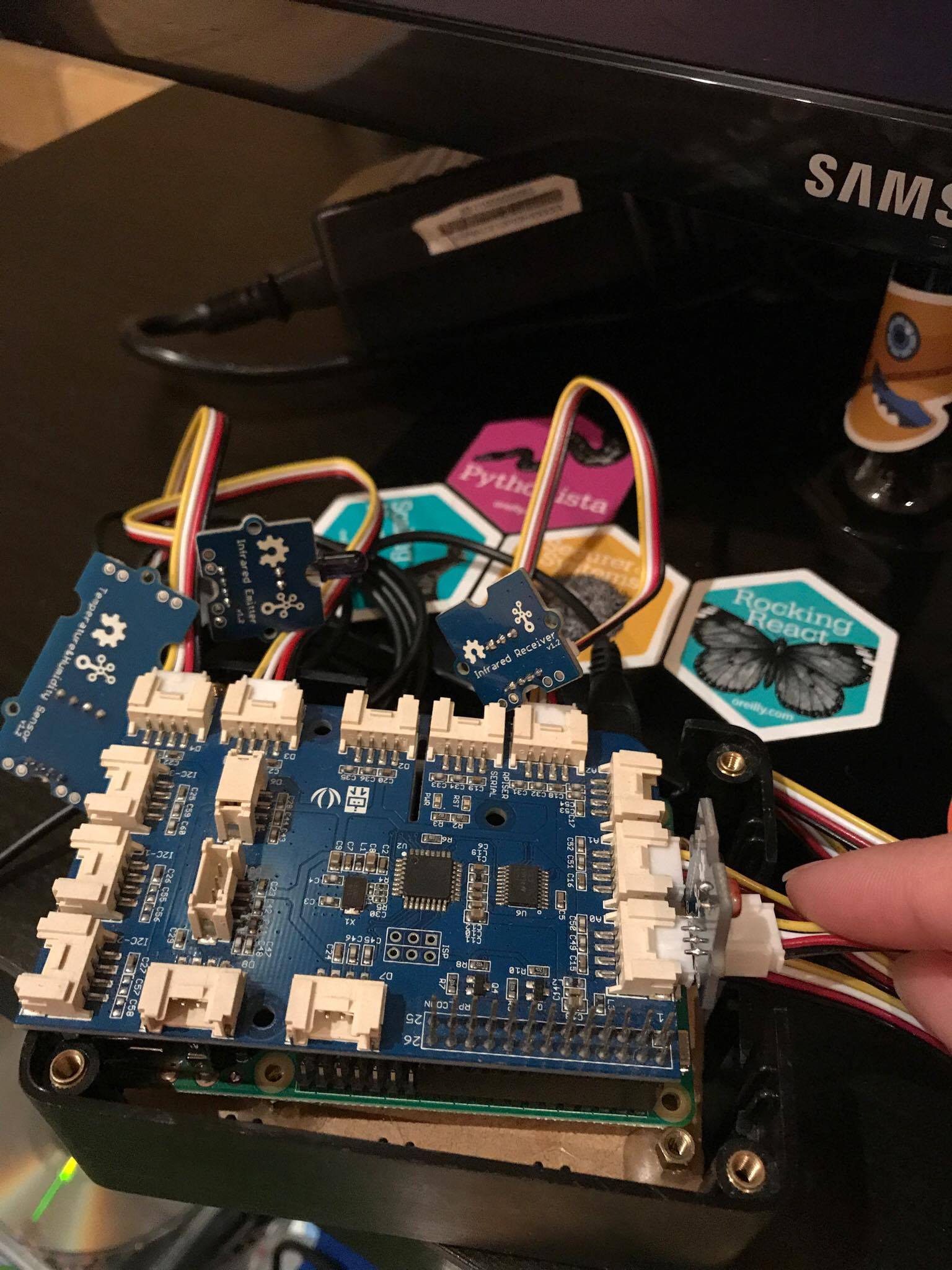
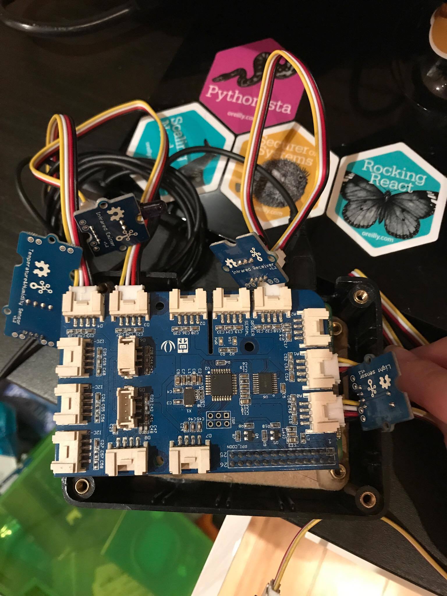
I have attached a picture of my current hardware configuration and its connections (rPi 3 + GrovePi Board + Infrared Receiver V1.2) as well as the remotes I have been testing with (Samsung AA59-00823A TV Remote, Iclebo Remote).
Unfortunately I have no logs to show, as I have not been able to get any response from either remotes. Hope this helps?
I’ve been doing tests with the Grove IR Receiver for a while and it doesn’t seem to work with the GrovePi.
Weird enough, it no longer works on a GoPiGo board with the same image on the micro SD Card.
We are going to do more tests and come up with a diagnostic for it.
I have come back to you as I have figured what is the problem. I have a solution for your problem, though I’m not sure if you’re going to like it.
The symptoms
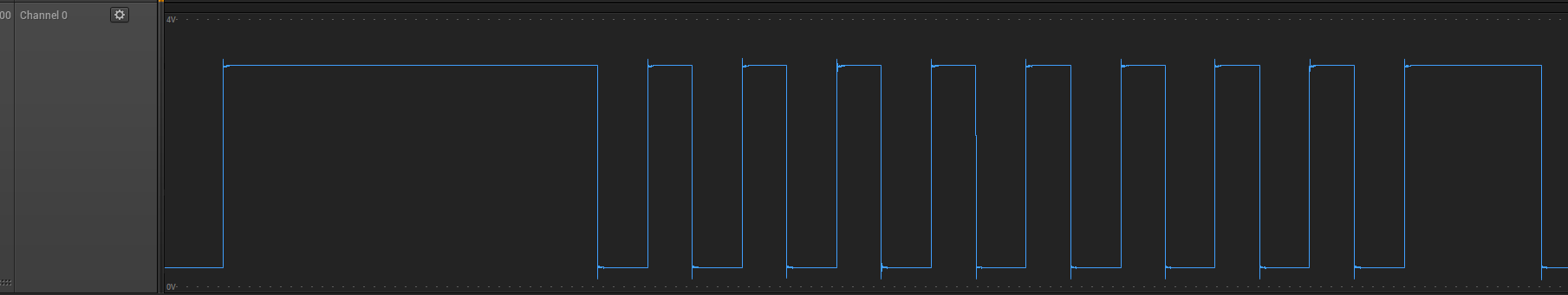
It has been seen that the Raspberry Pi doesn’t receive any signal on the serial port whilst the Grove IR Receiver is connected to the GrovePi and the remote control’s buttons are pressed.
Here’s a screenshot of what I would get when the remote control’s buttons are present: nothing. This has been done with a logic analyzer and what you see is the actual signal I get on the Raspberry Pi's RX serial port - the timeframe is 30 ms and the voltage of the signal is somewhere around 0.25V.
The issue
The problem was that there aren’t paired any pullup resistors - in our case we only need a single pullup resistor, and that’s for the RX pin of the Grove IR Receiver.
Since there aren’t pull-up resistors on the GrovePi, then the sensor should have had them, but it doesn’t appear to be the situation.
I’ve been experimenting with multiple pullup resistors (10kOhm, 4.7kOhm, 2.2kOhm) and I’ve seen that the Grove IR Receiver starts working with <= 1kOhm resistors.
The solution
Should you feel a bit adventurous, I have a solution for you. It involves a bit of soldering and a bit of time from you.
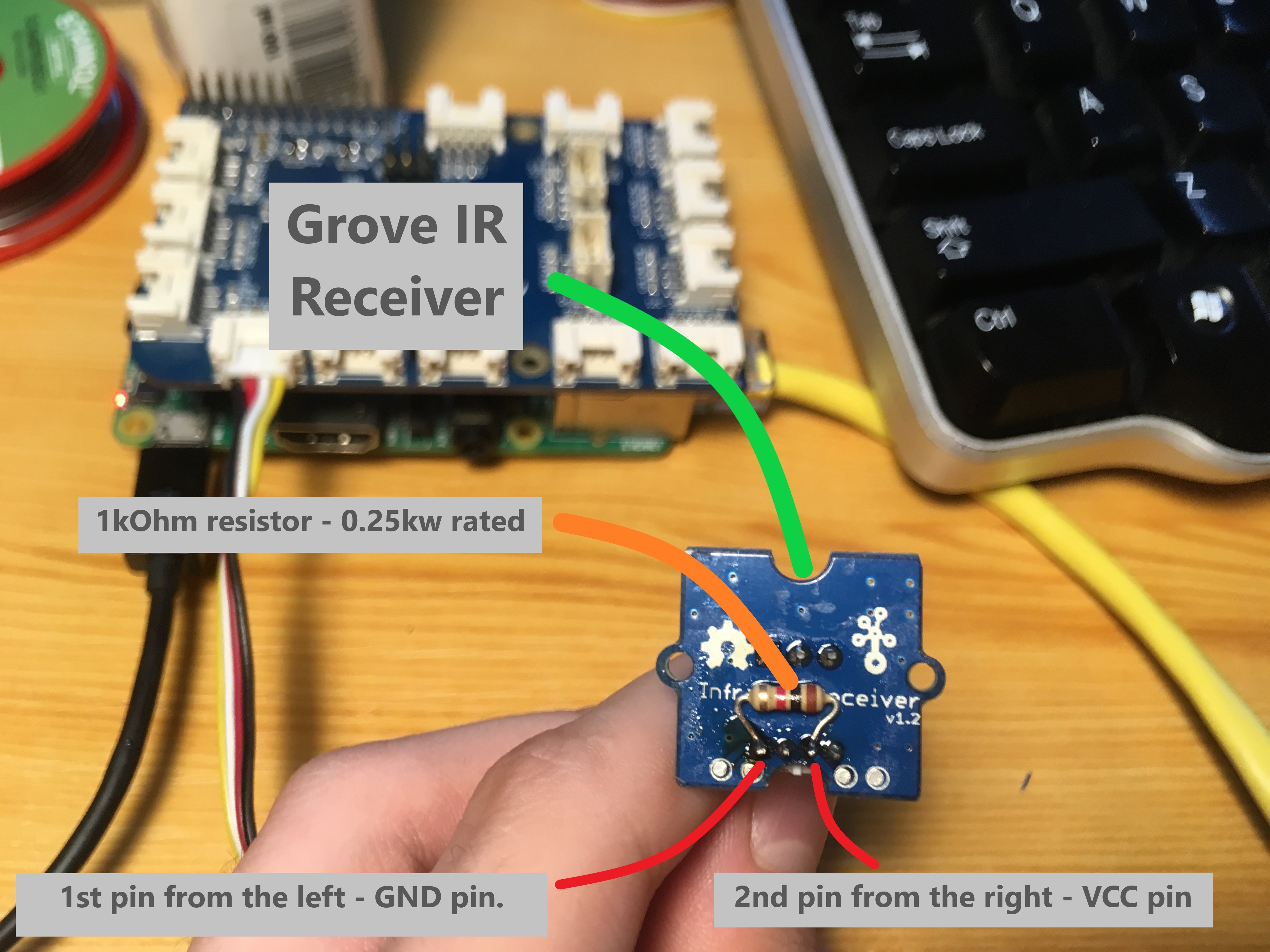
All you have to do is solder a 1kOhm resistor between the VCC and RX pins of the Grove IR Receiver sensor.
Here’s a photo of what I did - you can also find visual cues in the photo so that it can help you identify/understand what you have to do. (Apropo, there’s a small typo in the photo - instead of 0.25kw it should have been 0.25w).
After soldering the 1kOhm resistor between the VCC and RX pins of the Grove IR Receiver, I got the signal to show up on my logic analyzer.
Software considerations
I might also suggest you use the library that’s found on our GoPiGo repository.
It’s a lot more polished and I know for sure it works - it’s the one I’ve been playing with and it’s easier to use.
Conclusion
This looks like an incompatibility between Seeed's sensor and our products and I’m not sure if we can do more than guiding you on how to hack it and make it work, given these conditions.
If there are any more questions or if it still doesn’t work for you, please tell us.
I’ve been beating my head against this brick wall for a long time but, I’ve finally gotten to the point where the code in ~/Dexter/GrovePi/Software/Python/grove_ir_receiver.py will respond to a remote control and list the codes it has received!
It turns out the the note in the script about setting the pin to be used is misleading and the pin # should be the same as the digital port # that one has the ir_receiver plugged into. If I change it like so : grovepi.ir_recv_pin(8) and plug the sensor into D8, I get codes being displayed on the screen. This works and agrees with the current API documentation.
This also doesn’t require an extra resistor to be soldered to a v1.2 sensor. It may be needed when connected to the serial port but, the stock sensor seems to work on D8.
So… my follow on questions are :
How does one interpret the codes that are received?
Does part of it indicate the protocol?
OK. I guess I deserved that answer but, I’m not trying to use it as input. I’m trying to determine the protocol of the sending device. I’m interested in making modules that would be compatible with off the shelf laser tag guns and I’d like to understand what data is contained in the signals. I’ve gotten codes for several of them but, I’m not sure how the code maps to a protocol like NEC, Sony, etc.
Are you connecting it to a Grove port or directly to the Pi itself?
What is the output configuration of the sensor? Does it pull hard to the positive or negative rail? If they’re recommding a current limiting resistor, it’s probably a good idea to include it.
Do you really mean “protocol” (i2c, CAN buss, etc.), or do you really mean the “message frame format”?
Detecting the protocol itself will require extensive knowledge of the data format for each protocol.
Detecting the message format is easier, as you can read the raw data and see what changes as you press each button.
That’s outside the scope of what we can do here.
My recommendations are:
A logic analyser with a protocol decoder.
Protocol decoding software for the Pi if it exists.
Brute-force decoding by hand.
Search on line to see if anyone else has done it.
There are a few standard protocols, (like i2c) and you will have to either decode the bit-pattern by hand, or compare it to similar protocols.
Most remotes use similar message formats because they use the same/similar chips.
Some patterns I have seen are something like this:
[start of frame marker][manufacturer specific code][bit-mapped word(s) for each controller button][checksum][end of frame marker]
Of course your controller may map a message frame differently.
If you can, you may wish to open the controller and see what the IR encoder chip is and look up the datasheet.
Or. . . . You can go on-line and see if anyone else has tried to decode it.