Starting new thread since this isn’t directly odometry, but was spurred by that thread.
I built a little jig to make sure my GoPiGo3 was square to the near wall of my “roboland”. Ran the lidar and wrote a little program to capture 100 scan messages and then write the distances to a CSV file so I could look at it easily.
Things I learned:
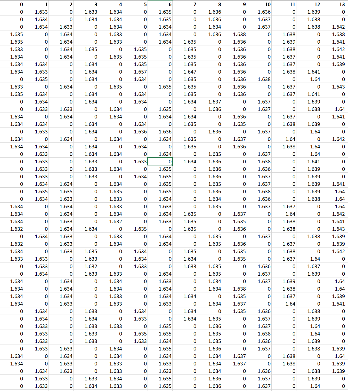
The lidar captures 720 values per spin, but inconsistently. On any given pass there are empty values - it’s non-random in the sense that certain angles seem to be missing values for several spins, and then the next half angle will be missing them. Here’s a slice of my spreadsheet to illustrate - top row is the position of values in the list, the rest are distances (in M)
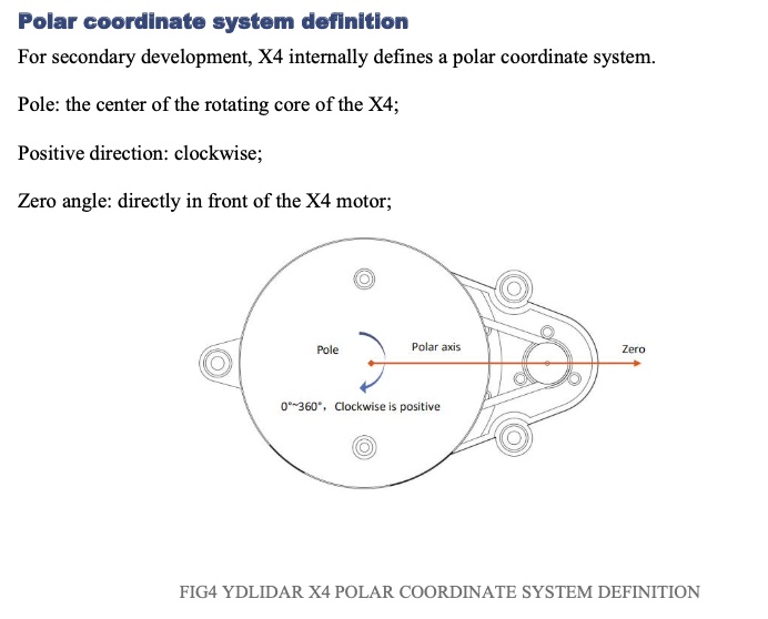
First surprise was that my zero point was straight back rather than straight ahead. Although as I thought about it that’s not so different from some examples I’ve seen with, say, a 180 scan where 0 was far left and 180 far right, so dead ahead was 90. I need to look around the different drivers and config files to see how the navigation stack is supposed to figure that out.
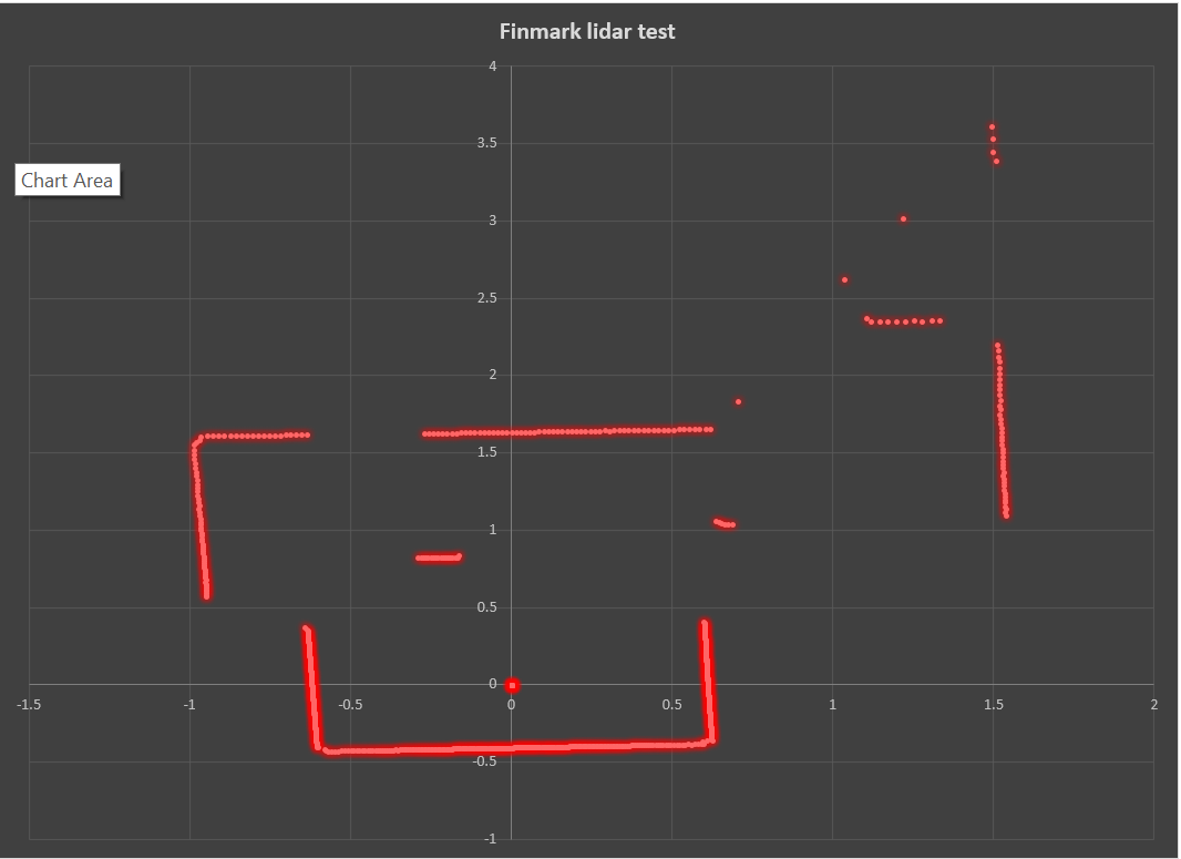
I took the average of all the non-zero distances at each point so I could generate a graph (converting the distance and angle into cartesian coordinates). First time I tried it my graph was reversed from what it should be. Then I remember positive spin in ROS is counter-clockwise, so maybe that has something to do with it, even though the lidar itself spins clockwise. I reversed the direction of the sequence of degrees and was actually able to generate a decent map from the points in excel.
Distances to the center of the lidar checked out with a tape measure. So I was happy enough about that. Still need to verify repeatability and check the distances with different initial poses.
Keep shaking till you remember the IMU corrects the gyroscopic drift using magnetometers which the LIDAR motor might influence - amount to be seen. So LIDAR may influence the IMU, and the IMU will eventually be the reference for where the LIDAR 0 degrees is pointing. At the moment, both Keith and I are using the encoders for the heading angle, but most ROS bots use the IMU for angles and encoders only for distance.
I actually turned off the mags when the IMU was on Carl, (and wrote a complete IMU ecosystem), because I wanted 0 heading to be the angle Carl sat on the dock, not the crazy magnetic north that was being influenced by the secret spy drones that were surely somewhere above my house driving the IMU 9DOF headings to be less accurate than the 6DOF configuration.
Of course the magnets in the LIDAR motors can influence the IMU.
When you realize exactly how minute the Earth’s magnetic field is with respect to other localized magnetic phenomenon like speaker field magnets, the gigantic magnet in the average microwave, and so on, it’s a wonder that magnetometers work at all.
I also suspect that the speaker(s) field magnets and the vibration motor’s magnets are much closer to a phone’s magnetometer/accelerometer than the LIDAR’s magnet is to yours.
I do not know for certain as magnetometer/accelerometer chip manufacturers are less than forthcoming about the design secrets of their chips, but I suspect that they can resolve minute differences within strong magnetic fields.
This is why most IMU-type units require several circles or figure-eights to establish a reasonable degree of confidence.
So, I would be surprised if these magnetic fields are causing that much trouble.
Of course, the easiest way to find out is to remove the LIDAR and see what the difference is in the IMU’s accuracy.
Likewise, the IMU can be removed to test the influence it may have on the LIDAR.
Even if the LIDAR’s software uses the IMU, I suspect that it is only incidental as the LIDAR should be able to stand alone, AFAIK.
No, the LIDAR itself does not use the IMU. All LIDAR measurements are relative to the LIDAR and ROS knows how to translate the LIDAR coordinate frame to the robot coordinate frame. ROS needs the IMU and/or encoders to translate the bot frame to the world frame, and thus the LIDAR measurements to the world frame.
Yes, the BNO055 has some interesting hard and soft field calibration and update functions. In fact they are frustratingly “smart” and not-controllable. You perform the tilting-figure-8 calibration maneuver until the IMU says “OK, I got it. I’ll take it from here” and then it tries to use the gyros and accelerometers to detect unexpected magnetic influences to adjust the calibration in real-time, and the magnetometers to correct the gyros. It lets you save off a calibration, but of course it is only going to treat reloading that specific moment in time calibration as a hint, and start building its own calibration again.
But I guess that should have been the subject of an IMU thread - this one is about the LIDAR. My bad.
I’ve learned more just watching the two of you than any five stacks of books could possibly hope to teach.
I am learning how both the IMU and the LIDAR interact, and how ROS sorts out the confusion.
For which I humbly thank you both.
IMHO, this is directly relevant, as “nothing helps to sort out confusion better than a restatement of the relevant facts” and how they interact with each other.
(Sherlock Holmes, Silver Blaze)
Hopefully this short digression has helped you both to clear your minds, re-focus, and find the ultimate solution.
To me, the inconsistency looks like you’re trying to read too many values too quickly.
Is it possible that:
It takes the LIDAR a certain number of spins to generate values for a particular angle?
While it is concentrating on angle “a”, it ignores angle “b”.
That graph has a strange resemblance to RGB (red, green, blue), interlacing as used in NTSC color TV*.
First picture frame:
First line: rgb rgb rgb rgb . . .
Second: gbr gbr gbr (etc)
Third: brg brg brg brg (etc)
Forth: rgb rgb rgb rgb (etc)
Second frame:
(start with the second line’s pattern in the first frame and continue from there)
Third frame:
(start with the third line’s pattern in the first frame and continue from there.)
When you’ve reached the fourth frame, you have built an entire color picture.
Maybe what you need is a software implementation of a quadrature detector?
* I originally wrote RGBL, but remembered that this pattern was from a General Electric color TV design, some of which, (the use of a 3.58mhz color subcarrier), was ultimately incorporated into the final RCA/GE color TV patents.
Additional thoughts:
I suspect that the reason that the groups are not even, (three readings, skip three, three more, skip, etc., is because the “frame rate” (LIDAR rotation rate) is not synchronized to the data aquisition rate resulting in the “picture tearing”. If you can, somehow, sync those two, you should see a regularly repeating pattern of data for each angular measurement in turn.
That is surprising since the YDLIDAR X4 Datasheet states the zero passes through the motor. It does show positive clockwise though, and as you noted ROS has the opposite chirality.
I think there is really only one factor that is easily selectable:
[YDLIDAR3]:Fixed Size: 1020
[YDLIDAR3]:Sample Rate: 5K     <--- Can be 5-12k
[YDLIDAR INFO] Current Sampling Rate : 5K    <--- my current configured sample rate
[YDLIDAR INFO] Now YDLIDAR is scanning ......
Scan received[1624198712776831000]: 567 ranges is [8.833922]Hz
Scan received[1624198712898864000]: 572 ranges is [8.756567]Hz
Scan received[1624198713013605000]: 571 ranges is [8.771930]Hz
and then there is the fixed board transfer Baud Rate: 128k
Although these are the selectable parameters for the ROS node:
ydlidar_ros2_driver_node:
  ros__parameters:
    port: /dev/ttyUSB0
    frame_id: laser_frame
    ignore_array: ""
    baudrate: 128000
    lidar_type: 1
    device_type: 6
    sample_rate: 5
    abnormal_check_count: 4
    resolution_fixed: true
    reversion: false
    inverted: true
    auto_reconnect: true
    isSingleChannel: false
    intensity: false
    support_motor_dtr: true
    angle_max: 180.0
    angle_min: -180.0
    range_max: 10.0
    range_min: 0.12                  <-- any range less than this is turned into zero in the publisher
    frequency: 5.0
    invalid_range_is_inf: false
Scan received[1624198712776831000]: 567 ranges is [8.833922]Hz <-- ~64 ranges per rev
The “bursty” nature of the data is interesting, as this output would have led me to believe it is taking one measurement approximately every six degrees, not a bunch at half degree intervals, then a pause before another bunch at half degree intervals. Some part of the pipe must be bottleneckin’ the dataflow.
@KeithW I can’t find a ydlidar.yaml file with your configuration parameters in your github. Are you using some defaults?
Also interesting that the ROS ydlidar node you are using in your “KFW-patch-1” branch has some message header value changes. The ROS2 node does not have those changes.
I was under the that he was executing the standard “and the next value IS! . . .” system/ROS call that anyone else would do.
. . . and that part of his problem was the amount of garbage data he received. (i.e. Why collect and view all that data if it’s not relevant and is never seen/used anyway?)
Good question - I haven’t had time to look. But when I make maps and even when I’ve done SLAM outside of my ‘roboland’ things seem to work fine. So I was surprised by the result. And I looked at the documentation - forward is towards the motors supposedly. Edit - I now see that you had already looked at that as well. Yeah - I’m still confused.
That was my thought as well - the onboard firmware doesn’t seem to capture quickly enough, or something.
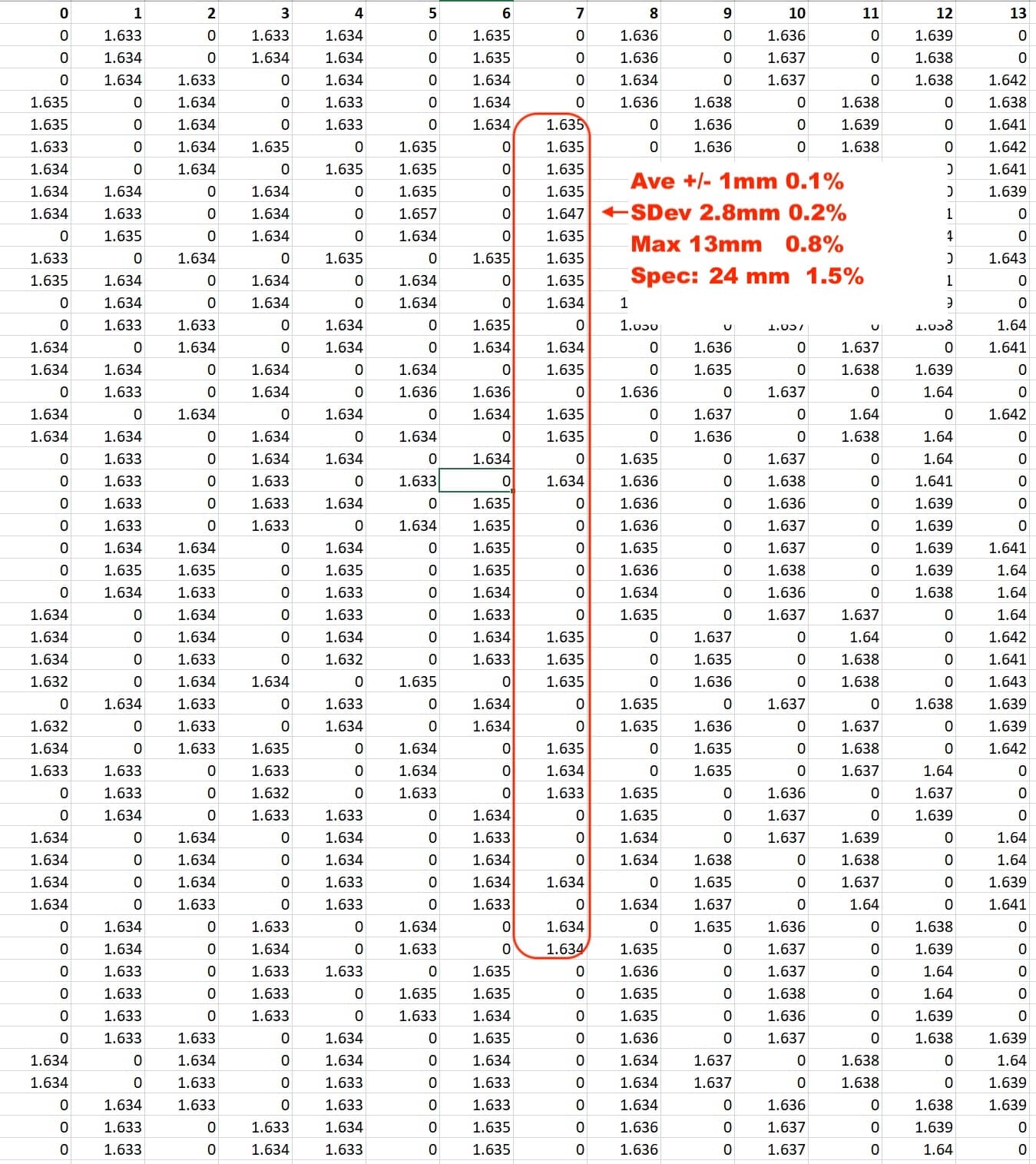
I thought about running the stats, but didn’t. If you factor in all of the 0 values the SD may actually be pretty high. For the actual readings, yes, the results seem pretty good.
I was surprised by how many 0’s I got, but based on that I had somewhat assumed that the software was treating the zeros as essentially null values - I hadn’t seen that confirmed anywhere.
ooh - I’ll have to look at that. Maybe that’s my problem.
Right now I’m not using the IMU at all, so I’m sure nothing is depending on the IMU.
I hadn’t thought about that - I was assuming that ROS would rely more on the accelerometers, but I realize I have no basis for this assumption. @jimrh 's concern about the motor on the lidar throwing things off seems reasonable.
Not at all. I’m sure we’ll have an IMU thread at some point. At the pace you’re going I suspect you’ll start it
The ydlidar node publishes a zero distance for any distance less than the min_value, and if no data is received.
All actual laser ranges are published relative to the center of rotation.
It is impossible for a range from the center of rotation to be 0, since the LIDAR has a 35mm minimum radius.
Thus 0 is a good “invalid” value. (The node does allow configuring NAN/infinity for “invalid” if desired.)
Probably to save message length in queuing and dequeuing time in industrial systems. Rather than publishing a variable size list of angles and a list of ranges, the structure allows for start/stop/increment angle (three values) and the list of ranges (1 to a max of 719 for our 360 by half degree LIDAR). In the never misses a beat case this would save 716 floats.
Since ROS is primarily targeted for industrial robots with costly sensors, perhaps the waste, in my case only 65 good values, of 589 to 654 floats transmitted is of no concern to anyone?
sensor_msgs/LaserScan (/scan)
# Single scan from a planar laser range-finder
#
# If you have another ranging device with different behavior (e.g. a sonar
# array), please find or create a different message, since applications
# will make fairly laser-specific assumptions about this data

Header header            # timestamp in the header is the acquisition time of
                         # the first ray in the scan.
                         #
                         # in frame frame_id, angles are measured around
                         # the positive Z axis (counterclockwise, if Z is up)
                         # with zero angle being forward along the x axis

float32 angle_min        # start angle of the scan [rad]
float32 angle_max        # end angle of the scan [rad]
float32 angle_increment  # angular distance between measurements [rad]

float32 time_increment   # time between measurements [seconds] - if your scanner
                         # is moving, this will be used in interpolating position
                         # of 3d points
float32 scan_time        # time between scans [seconds]

float32 range_min        # minimum range value [m]
float32 range_max        # maximum range value [m]

float32[] ranges         # range data [m] (Note: values < range_min or > range_max should be discarded)
float32[] intensities    # intensity data [device-specific units].  If your
                         # device does not provide intensities, please leave
                         # the array empty.

Compact Message Definition
std_msgs/Header header
float32 angle_min
float32 angle_max
float32 angle_increment
float32 time_increment
float32 scan_time
float32 range_min
float32 range_max
float32[] ranges
float32[] intensities