Maybe Seeed came up with a different US sensor, because the one they had when we launched our Time of Flight was ABYSMAL.
3 Likes
These readings, both @cyclicalobsessive’s and mine appear to have a tolerance of about ±5 mm.
I, myself, don’t consider that excessive as I am not using the distance sensor to accurately map a room, but simply to let me know, more or less, how far away I am from something.
If I need better accuracy than that, there are small millimeter-band robotic-sized radar units out there that give sub-millimeter accuracy. Of course, they cost like one of Tom Coyle’s Nitro-burning Mega-Bots. 
Me, this is way good enough.
What really gets me laughing is the way the title, and the logo, fit together at the top of the screen:

2 Likes
You need to change the list size to 300, and not print the list. Running the existing program is repeadly testing 10 readings.
2 Likes
Oh, NOW you tell me. . . .
I’ll do that tomorrow.
1 Like
Indeed they say this is version 2.0 of the sensor.
2 Likes
Here’s what I’m running (now)
#!/usr/bin/python3
#
# distSensorError.py

"""
Continuously measure distance in millimeters, printing the average and individual readings
"""
import numpy as np

from di_sensors.easy_distance_sensor import EasyDistanceSensor
from time import sleep

ds = EasyDistanceSensor(use_mutex=True)
distReadings = []

count = 0
while count < 300:
    distReadings += [ds.read_mm()]
#    if (len(distReadings)>9 ):  del distReadings[0]
#    print("\nDistance Readings:",distReadings)
    print("Average Reading: %.0f mm" % np.average(distReadings))
    print("Minimum Reading: %.0f mm" % np.min(distReadings))
    print("Maximum Reading: %.0f mm" % np.max(distReadings))
    print("Std Dev Reading: %.0f mm" % np.std(distReadings))
    print("Three SD as a percent of reading: %.1f %%" % (3.0 * np.std(distReadings) / np.average(distReadings) *100.0))
    count += 1
    print("count is", count, "seconds\n")
    sleep(1)

print("5 min worth of readings. . .")
Readings test - first try at (appx) 60 cm.
Average Reading: 625 mm
Minimum Reading: 613 mm
Maximum Reading: 638 mm
Std Dev Reading: 5 mm
Three SD as a percent of reading: 2.2 %
count is 300 seconds

5 min worth of readings. . .
Second try:
Average Reading: 624 mm
Minimum Reading: 612 mm
Maximum Reading: 636 mm
Std Dev Reading: 5 mm
Three SD as a percent of reading: 2.2 %
count is 300 seconds

5 min worth of readings. . .
BTW, it takes about 30 - 40 seconds before the readings settle down to essentially what you see here.
What I see here is a tolerance band of one stinkin’ centimeter! (10 mm), or expressed differently, ±5 mm.
I can live with a 1 cm tolerance band.
You should try this on Carl and Dave and see what you get after five minutes.
1 Like
Here is a 300 list size program:
#!/usr/bin/python3
#
# distSensorError.py

"""
Continuously measure distance in millimeters, printing the average and individual readings
"""


import numpy as np

SAMPLES = 300

from di_sensors.easy_distance_sensor import EasyDistanceSensor
from time import sleep

ds = EasyDistanceSensor(use_mutex=True)
distReadings = []

while True:
    distReadings += [ds.read_mm()]
    if (len(distReadings)>(SAMPLES-1) ):  del distReadings[0]
    print("\nDistance Readings:",len(distReadings))
    ave =  np.average(distReadings)
    min =  np.min(distReadings)
    max = np.max(distReadings)
    minError = (min-ave)/ave * 100.0
    maxError = (max-ave)/ave * 100.0
    print("Average Reading: %.0f mm" % ave)
    print("Minimum Reading: {:.0f} mm  Min Error: {:.2f}%".format(min,minError))
    print("Maximum Reading: {:.0f} mm  Max Error: {:.2f}%".format(max,maxError))
    stdDevReading= np.std(distReadings)
    stdDevError = (stdDevReading)/ave*100.0
    print("Std Dev Reading: {:.0f} mm  StdDevError: {:.2f}".format(stdDevReading,stdDevError))
    print("Three SD as a percent of reading:  {:.1f} %".format(3.0 * stdDevError))
    sleep(1)
IR Sensor On Carl at 846mm
Distance Readings: 299
Average Reading: 846 mm
Minimum Reading: 819 mm  Min Error: -3.17%
Maximum Reading: 868 mm  Max Error: 2.63%
Std Dev Reading: 8 mm  StdDevError: 0.94%
Three SD as a percent of reading: 2.9 %
IR Sensor on Dave at 838mm:
Distance Readings: 299
Average Reading: 838 mm
Minimum Reading: 813 mm  Min Error: -2.97%
Maximum Reading: 869 mm  Max Error: 3.72%
Std Dev Reading: 10 mm  StdDevError:  1.19%
Three SD as a percent of reading: 3.5 %

Second set of 300:

Distance Readings: 299
Average Reading: 837 mm
Minimum Reading: 798 mm  Min Error: -4.66%
Maximum Reading: 878 mm  Max Error: 4.90%
Std Dev Reading: 12 mm  StdDevError: 1.42
Three SD as a percent of reading: 4.3 %
The StdDevError and Three SD Error are over 300 readings.
Three SD says “Probably the worst readings will be +/- this percent of the real reading”.
The Min/Max Error are single readings.
Note: If anything changes during test (like accidentally walking between the bot and the target), the test is invalidated, so must restart.
1 Like
What I see from your result is single readings will be +/- 14mm or +/-2.2% which is better than the device spec, and nearly twice better than Carl or Dave’s IR sensor.
Additionally if all Charlie is worried about is bumping into something, stopping at 200mm +/- 4mm is certainly tolerable.
Here is where it might really hurt: Using the IR Distance sensor to measure the robot’s angle with a wall up ahead with a 45 left, 90 ahead, 45 right measurements.
But then again, we would have to repeat the test with a 45 degree incident target to know what the error is for both sensors for a target that is not exactly norm to the sensor.
2 Likes
Which begged the question what does it look like with the ultrasonic on Dave:
Distance Readings: 299
Average Reading: 802 mm
Minimum Reading: 800 mm  Min Error: -0.21%
Maximum Reading: 803 mm  Max Error: 0.16%
Std Dev Reading: 0 mm  StdDevError: 0.06
Three SD as a percent of reading:  0.2 %
2 Likes
Wow, that would be hard to keep the data straight for testing: - single vs. 3 to 5 reading bursts as the bot or target changes known positions to estimate the error rate on a moving bot.
Can’t use the encoders to adjust the reference distance because they have an error rate as well.
I guess I’d have to
- set target at a known distance, input to test
- run the single and burst measurements
- move the target 100mm, input to test
- run the measurements again
- repeat for a total of five to 10 distances
The problem with that is having to measure the reference distances to millimeter accuracy, where with the stationary test the average of a bunch of readings is the reference.
I remember doing some “error rate vs number of averaged readings” test very early on to decide on how many readings are needed for a trustworthy distance and settled on 3 quick readings averaged.
2 Likes
Which begs two additional questions:
-
What was wrong with the way I modified your original program to take 300 samples?
-
Do you really need sub-millimeter accuracy and incident angle?
AFAIAC, sub-millimeter accuracy is file if you’re doing a land survey, analyzing a Ramen spectrometer’s output, or examining pathogens under a microscope, but for a robot wandering around in a room, a rough approximation of where the walls are and their distances should be fine. As you get closer to the wall, the resolution improves until you get “close enough” that the actual distance really matters, (within about 10-20 cm or so).
Your own eyes can’t measure distance or incident angle to the kinds of accuracy you’re demanding of Carl and Dave. And you don’t really need it - you know when you’re “close enough” and precise incident angle isn’t really necessary.
You can get that kind of repeatable accuracy, but it’s going to really cost you for a millimeter band radar ranging device.
The next question is: Are you using the optical processing capabilities fully and effectively? I’m no expert on this, but it seems you should be able to use your fancy-pants kickstarter camera assembly to do more than you’re using it for.
What say ye?
2 Likes
OK, here’s data from Charlie for you. I’ve limited the number of samples taken to 300 - it bails after that.
I can confirm one limitation: Black surfaces.
When on my table, pointing at the front of my (black) printer, with a shiny surface at about 30-45 degrees, the readings are all over the place.
First test at 60 cm.
Distance Readings: 299
Average Reading: 623 mm
Minimum Reading: 601 mm  Min Error: -3.48%
Maximum Reading: 640 mm  Max Error: 2.79%
Std Dev Reading: 6 mm  StdDevError: 1.04
Three SD as a percent of reading:  3.1 %
The number of samples so far is: 300
300 samples have been collected.
Second series:
Distance Readings: 299
Average Reading: 623 mm
Minimum Reading: 601 mm  Min Error: -3.48%
Maximum Reading: 640 mm  Max Error: 2.79%
Std Dev Reading: 6 mm  StdDevError: 1.04
Three SD as a percent of reading:  3.1 %
The number of samples so far is: 300
300 samples have been collected.
What do you think?
My opinion:
It is perfectly fine for its intended purpose.
2 Likes
Wrong?? I don’t see anything wrong with the code you posted.
I am not seeking “sub-millimeter accuracy”.
My interest in knowing the distance measurement error effect on the incident angle computation comes from:
- Wall Follow Initiation Turn: What angle does bot need to turn to initiate wall following headed parallel to wall?
- Docking Approach Turn: What angle and drive distance is needed to arrive at the “docking approach point”?
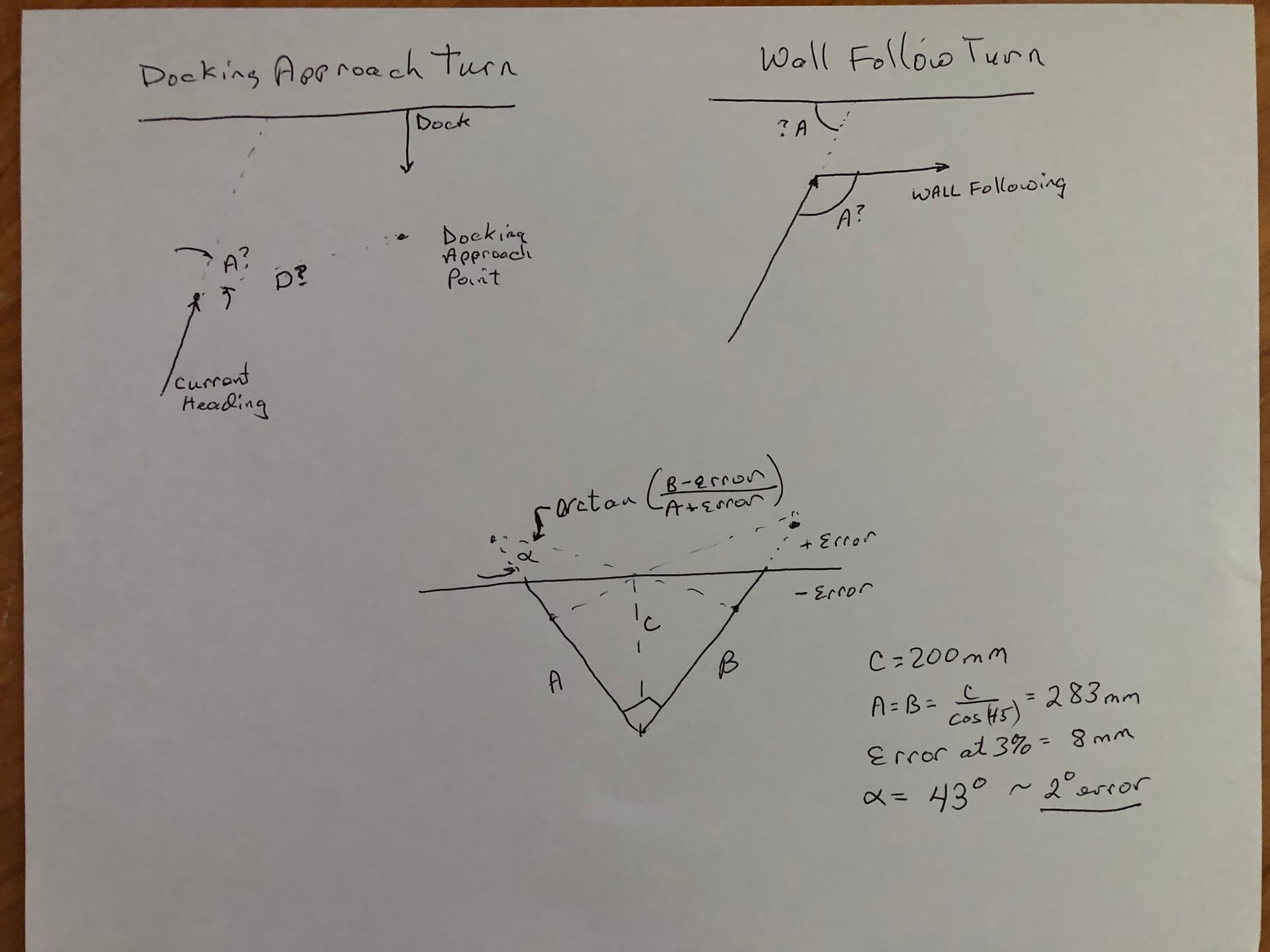
Turns out I was wasting cycles as the angle error resulting from a +/- 3% distance measurement error will be roughly +/- 2 degrees. The robot’s commanded turn angle accuracy is roughly that.
A real robot needs to live with error - error in measurements, error in command response, and errors in the programmer’s mind.
Well, Duh. I am a procrastinating perfectionist afraid of reality. It is a lot easier to distract myself by investigating VScode native and remote, and then with investigating IR sensor vs US sensor.
2 Likes
Before I “saw” that LIDAR was totally blind to my black UPS at any non-normal incidence angle, I really had no understanding of what Carl or Dave might be “seeing” with the IR TimeOfFlight Distance Sensor.
I had a faint concept of the distance sensor having a “beam width” and that obstacle size and shape could affect if the obstacle is detected, but I did not have a clue that color or incidence angle could affect the measurement.
2 Likes
The next next question would be:
- Are you over-engineering this?
(i.e. Are you making this more complicated than it needs to be?)
The reason I ask is that this is something I do too. For example:
When working on my New Remote Camera Robot project, I needed to calculate the ratio of the wheel speeds when making a turn. Obviously, the further the joystick is moved to the right or left, the sharper the turn will be. So I decided to trot out some trig to determine the magnitude of the vectors and use the magnitude of these vectors and their sign to determine the wheel rotational velocity in either direction, for both the inside and outside wheels.
Not only did I have to deal with left and right, but also forward and backward motion while making the turn.
And what happens when the joystick crosses the “X” axis in either direction? I need to be careful there because if I am commanding full speed in one direction and suddenly change it to full speed in the other, I can damage the motors or burn up the “H”-bridge that drives them - so I have to compensate for that too.
I spent hours and hours, becoming days and days, working on refining the calculations to make them quick and easy, substituting addition and subtraction for multiplication and division - and using quick-and-dirty tricks to calculate sine, cosine and tangent, (along with the corresponding arc-functions). I even enlisted the help of my brother who has a PhD in math to critique my techniques.
It was beautiful! It was a mathematical dream come true! And I still had this nagging feeling that I was missing something. . . . I kept hearing this little voice: “Inside every large program there is a small program struggling to get out.”
So, I looked again at the axis values - I even drew a circle-chart and plotted the X-Y magnitudes for various joystick positions - and then the light-bulb went on: The best and fastest optimization for complex trig is no trig at all - in fact the fastest optimization is no math at all! (Well, a tiny bit of math.)
I discovered that I could use the absolute position of the x and y axes to determine direction, velocity, and wheel ratio with the most trivial math possible. My biggest challenges were calculating percentages and rounding to the correct precision.
I showed this to my brother and he responded with a face-palm too.
======================
Maybe you need to step back and try to find a stupidly simple way to do what you want, even if it doesn’t have the decimal precision you desire?
What say ye?
2 Likes
Yes, but “stupidly simple” is simply not simple to my simple mind.
2 Likes
Here’s a simplification:
- Approach until you get “close enough”.
- Turn in the required direction until the distance becomes huge. (i.e. No longer pointing at the wall.)
IMHO, your biggest problem with docking is that you’re doing it backwards. Using self-docking vacuum robots as an example, they always dock head-in so they can refine their position continuously and head toward the goal.
You have your robots designed to back-into their docks so none of the sensors can help you.
As I see it, you have two choices:
- Figure out a way to determine when the robot is directly in front of the dock and then turn to back in - with a mechanical guide to help you.
- Use a set of three line-follower sensors, (if you can get them on three different i2c addresses), and a narrow-beam IR source, (maybe an IR laser?) directly above the dock.
- One line-follower on the left, one on the right, one on the back.
- Drive in the general direction of the dock, adjusting to be some desired distance.
- Drive toward, (roughly parallel) the dock until a side sensor sees the IR beam. Continue until the beam is centered on the sensor.
- Rotate in the appropriate direction until the beam is centered on the rear sensor.
- Drive backward - correcting if the beam drifts from center.
- The mechanical guide should then help you dock accurately.
Or something like this.
I really think you need to sit down with a piece of paper and forget the trig, calculus, and all the engineering statistics - and figure out how to do it with cardboard and sticky-tape.
What say ye?
1 Like
Nah - I need to sit down with VSCode and test some wall following, instead of constantly thinking about it.
2 Likes

That’s one of the beauties of VS Code and GitHub - you can play and play and play and play and - if nothing’s working - back all the way out and try something different.
Tags are your friend! They serve as “stakes in the ground” marking a particular point in your coding. If you paint yourself into a corner, you can revert back to the nearest, (or any), tagged point very easily and start fresh.
One thought just came to mind. Have you tried thinking like a pilot instead of a robot?
Assume you have some way of marking the docking station - an IR beam or laser pointing directly out from it. Think like a pilot and simply drive in the direction of the dock - wherever it is - until you cross the “localizer beam” and then use that to home in on the dock. No wall following needed.
1 Like
I have the short range unidirectional beam VOR (two LEDs with a separator), but Carl is not great at seeing them until he gets close. The have-to-turn-around part is quite limiting as you mentioned.
The wall following is a whole separate interest as you know - I’ve been thinking on that forever.
2 Likes