Success!
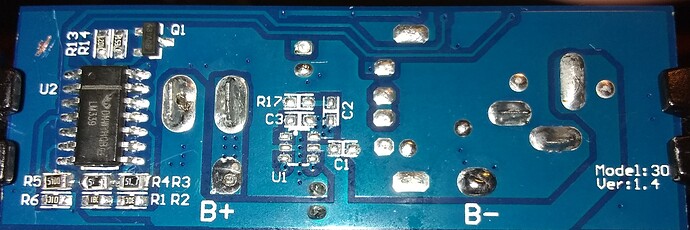
Replacing R3, R4, and R5 with 510Ω 5% resistors did the trick!
If you look at the three resistors directly under the large IC, you will notice the, (sloppy), change to 510Ω each.
With those values, the trip points are almost exactly on 11.5, 11.0, 10.5 and 10.0.
That should give us the spread we need to accurately gage the current life remaining.
It turns out that 1% resistors are not needed because the 35kΩ scaling resistors, (R1 + R2), swamp out any variation in the rest of the ladder network.
Even those aren’t absolutely critical. If they continue to use the existing values for R1, R2, and R6, everything should be fine.
@cleoqc
@mitch.kremm
Is it possible for you to make this modification to a couple or three battery packs?
I’d like to see a wider sample set.
Everyone else:
If you have the time, courage, and soldering skill to make these changes, I’d appreciate knowing how it works for you.
It would be nice to see what results others see.
I am going to reassemble the pack, charge it, put it on Charlie, and see how it plays out.
I expect it to be dead-on based on my static voltage test.
Note:
I unsoldered the two leads from the batteries, completely removed them, and taped over the bare ends of the wires before I did anything else.
Lithium batteries may not necessarily frighten me, but I sure respect the livin’ heck outta them!


