TalentCell YS1203000 "State of charge" monitor

All valid points.

One of the design constraints is the lack of a calibration trimmer and the need to use resistor values that actually exist.

This is all theoretical at this point. I still have to “fit the curve” to real world conditions.

As I am sure you’ve guessed, EE and circuit design isn’t always simple. :wink:

2 Likes

Visually at least, the knee of the discharge curve doesn’t begin to get really radical until about 10v, with 30 min run time remaining.

That seemed to be a reasonable place to put the last LED flip.

By the way, the delta should be around 0.6v, my bad.

2 Likes

I could place the flip points at 11.5, 11.0, 10.5 and 10.0 which would evenly space them.

This assumes that I can get actual resistor values that will give me that interval.

2 Likes

Update.

I’m guessing that the original divider network was scaled for NiMH batteries since it was scaled to trip each LED at 11.8, 10.8, 9.8 and 9.1v. If we assume a certain amount of linear space after 9.1 volts, then it smells strongly of NiMH.

Or, they divided up the space between 12.0 and 8.2 (or so) and chopped it up into equal segments, not considering that there is a sharp knee beginning at about 10 volts.

I have re-calculated the values and we can get very near our ideal scaling if we change the 1k resistors to 499 ohm 1% resistors.

The new trip points become 11.6, 11.1, 10.6 and 10.1 volts.

Not as simple as I wanted, but reasonably doable.

@cleoqc and @mitch.kremm

What do you think of this as a modification suggestion for TalentCell?

It’s a change of three of one value for three of another.

I am going to try to get some 5% smd resistors and try them.

2 Likes

Did a search of all the local dealers, including Amperkot, who has all kinds of stuff for the Pi, but NOBODY even THINKS about this item for the Pi.

Micro:bit? Yup! Got 'em.
Pi? Are you kidding?!

The closest thing I found was articles about the Google AIY kit.

If anyone wants to send me one, talk to Nicole and Mitch first as it’s a three-cornered pain in the tush.

Spoiler:
You can’t.
You can only send stuff like that to registered companies and only by DHL unless you want it to get stolen.

Bummer.

2 Likes

Success!

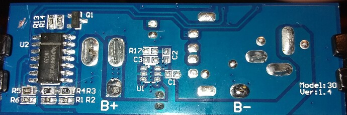
Replacing R3, R4, and R5 with 510Ω 5% resistors did the trick!

If you look at the three resistors directly under the large IC, you will notice the, (sloppy), change to 510Ω each.

With those values, the trip points are almost exactly on 11.5, 11.0, 10.5 and 10.0.

That should give us the spread we need to accurately gage the current life remaining.

It turns out that 1% resistors are not needed because the 35kΩ scaling resistors, (R1 + R2), swamp out any variation in the rest of the ladder network.

Even those aren’t absolutely critical. If they continue to use the existing values for R1, R2, and R6, everything should be fine.

@cleoqc
@mitch.kremm

Is it possible for you to make this modification to a couple or three battery packs?

I’d like to see a wider sample set.

Everyone else:
If you have the time, courage, and soldering skill to make these changes, I’d appreciate knowing how it works for you.

It would be nice to see what results others see.

I am going to reassemble the pack, charge it, put it on Charlie, and see how it plays out.

I expect it to be dead-on based on my static voltage test.

Note:
I unsoldered the two leads from the batteries, completely removed them, and taped over the bare ends of the wires before I did anything else.

Lithium batteries may not necessarily frighten me, but I sure respect the livin’ heck outta them!

2 Likes

(Amazing) work Jim. Congrats on the “simple” success. You really worked hard on this one.

2 Likes

You just went down to your local Walmart and picked up some surface mount resistors?

My junk box is feeling shamed.

2 Likes

I was hoping for a simple fix that anyone with the requisite skill and courage could do.

As far as the lithium batteries are concerned, the large pads marked “B+” and “B-” were where the red and black wires from the battery module attached. I unsoldered them and then folded a piece of tape across each of the exposed wires to avoid inadvertent short circuits.

Once that was done, I was free to probe around and do whatever I wanted without worries.

An old dog with a soldering iron like you could do this in your sleep. That is, once the battery is disconnected!

2 Likes

I’ve had those nightmares. Dave’s battery pack is quietly, and hopefully safely working with the LEDs obsoleted.

Sorry, I can’t contribute further to the validation effort.

2 Likes

Actually, yes - sort-of.

About five miles south of here is a place called “Chip & Dip” which is like an Arrow Electronics or a “You-Do-It”.

They have a wide variety of parts, all of which are hideously over priced.

There are strange gaps too. Much for the Arduino, not so much for the Pi.

They have kits, (boxes), that have a bunch of standard 5% resistor values but no corresponding kits of capacitors.

2 Likes

I guess to each his own.

You won’t mess with the batteries and I won’t touch ROS with someone else’s ten foot pole!

It’s a good thing that we’re both working on this stuff. :+1:

1 Like

As far as “safely” is concerned, I wouldn’t worry. After several charge/discharge/recharge cycles the batteries don’t even get slightly warm - which is more than I can say for my NiMH cells. After a few cycles they became quite warm to the touch, and that’s on a (supposedly) smart charger.

I think you should worry more about hurricanes than Dave’s batteries.

2 Likes

I think you are correct, but distraction with my “toys” keeps me calm and sleeping well (except when Carl or Dave get sick.)

2 Likes

Part of that “requirement” was that a simple fix is more likely to be considered and implemented by TalentCell than one with multiple cuts-and-jumpers.

In this case it’s as simple as changing a couple of component reels on their pick-and-place machines with components they probably already have in stock.

The “excess” 1k resistors won’t go to waste either - they’re a very commonly used value.

Likewise, if someone wants to give the update a try, it’s not that difficult - assuming you have steadier hands than mine!

2 Likes

I’ve done VERY limited surface mount soldering. Looks pretty good to me. Congrats!
/K

2 Likes

I’m used to MIL-SPEC. . . .

As a first-of prototype, it’s OK - but I expect the second one to be a lot cleaner.

Like you and your visual models. Maybe the robot does what it’s supposed to do, but if the robot goes one way and the wheels go another in the model, that’s not good enough. :wink:

2 Likes

Update:

I am currently working on building a full-fledged bench power supply so I can characterize both the battery and the robot.

@cleoqc

What are the power signalling voltages for the GoPiGo’s LED? ( Green, yellow, and red)

2 Likes

The most you were able to get from the guy that designed that part of the bot:

You go guy! Now we’re going to get some answers.

2 Likes

There’s also a purple colour that can show up. This means the Pi is shutting down but there’s still power going.

2 Likes