Greetings!
Ref: A New Bot Was Spotted:
[b]https://forum.dexterindustries.com/t/a-new-bot-was-spotted/5783/3[/b]
My poor bot has had its issues while I’ve been learning my way around both robotics in general and the GoPiGo in particular. After the second antenna broke off, (and since it was smashing face-first into everything), I decided it was time for a clean-up, spruce-up, and a front bumper.
First, (just in case @cyclicalobsessive is watching!), I have decided that the 'bot has earned a name. I have decided to name it “The Bug Mobile”, also known as “Charlie” after the hapless Charlie the Tuna featured on some older Chicken-Of-The-Sea tuna commercials.
By way of explanation:
In these commercials Charlie the Tuna wants to be a “Chicken-Of-The-Sea” tuna and keeps trying to impress the company with his good taste - by doing things like attending the opera, dressing up, listening to classical music, etc. The tag line at the end of the commercials was always “Sorry Charlie!” (“We don’t want tuna with good taste, we want tuna that tastes good!”)
Since this 'bot’s life has had a rocky start, (battery problems, programming issues, a small fire, smashing into things, and so on), every time my poor GoPiGo does something unexpected, I laugh and say “Sorry Charlie!”
Without further ado, the New and Improved Bug Mobile!
(Drum Roll. . . . . . .)
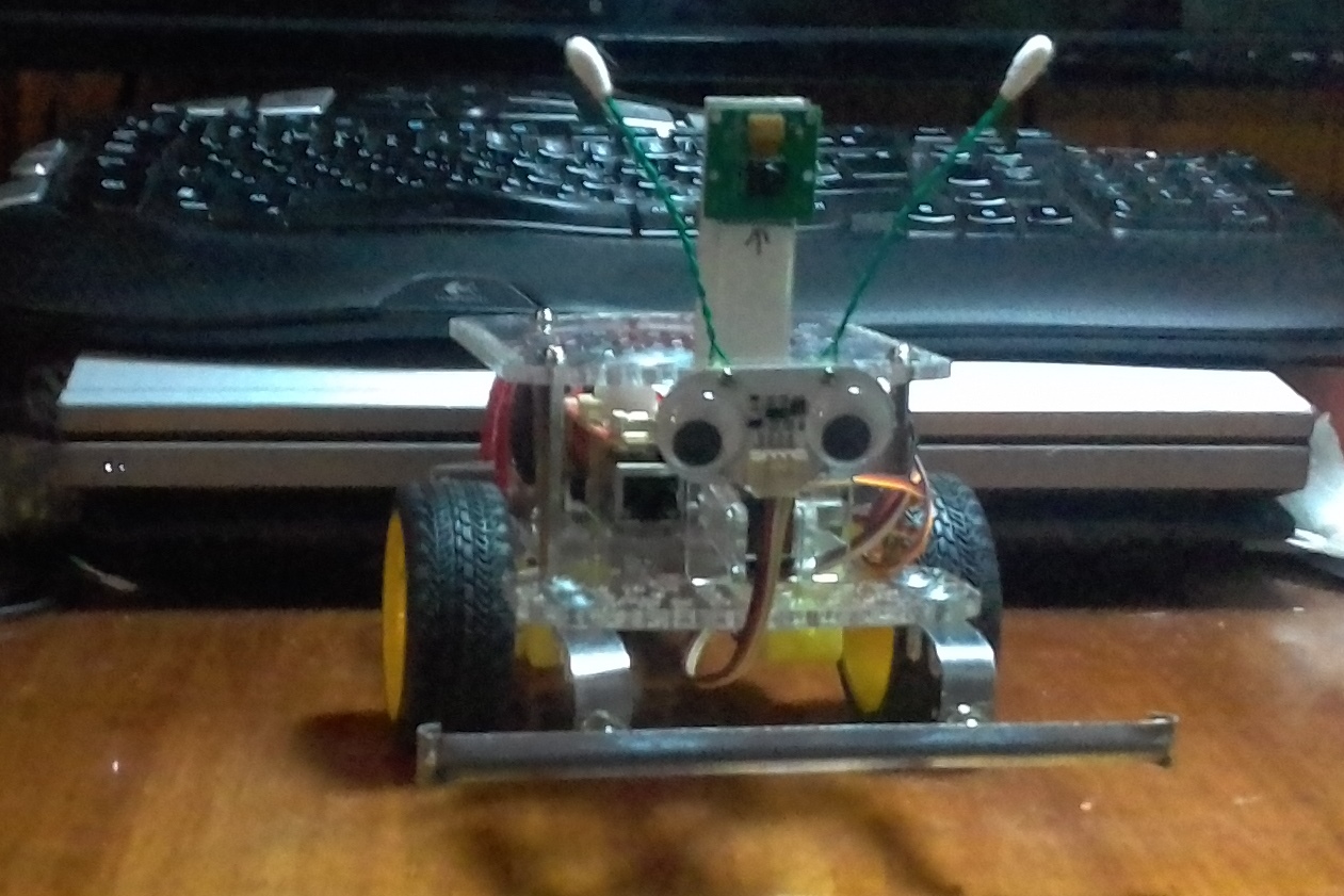
Here you can see his new front bumper and the antenna upgrade. Towering between the antennae is his new Pi Camera. (Actually, it’s an older camera, but I finally got it working.)
What I really want to do with the camera installation is make up a flexible cable for the camera and mount it, along with the “eyes”, (distance sensor), on the front servo. I can’t do that with the supplied ribbon-cable, (I tried!), because the camera’s white ribbon-cable isn’t flexible enough to make sweeping turns over an arc of almost 180 degrees.
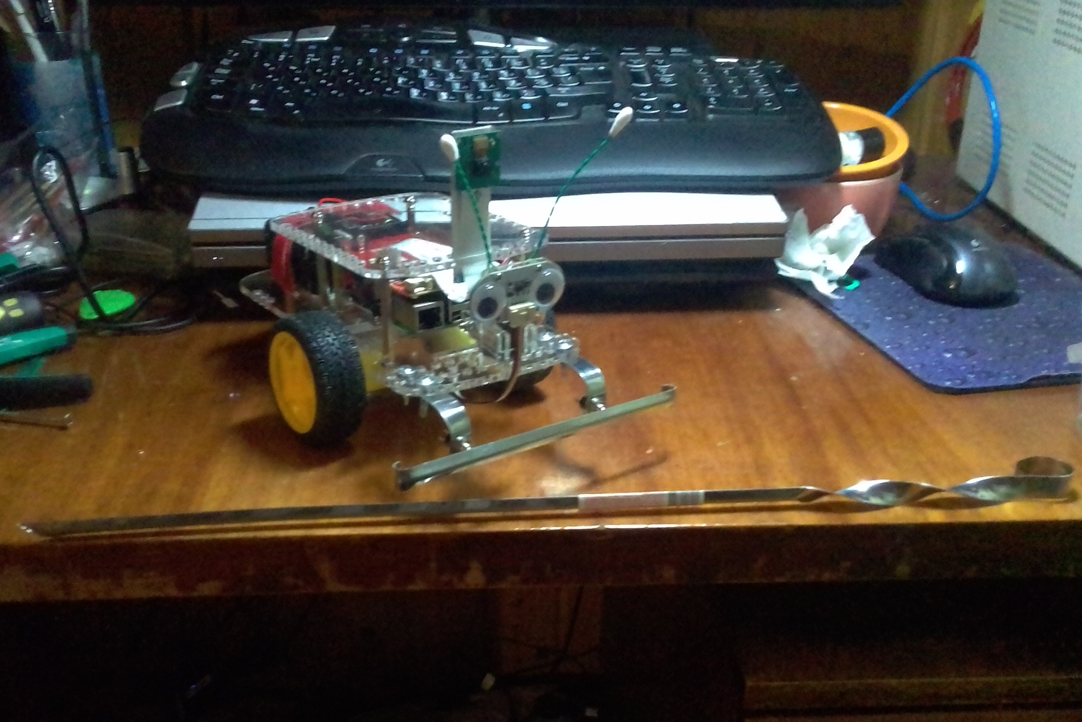
Here’s Charlie in profile, posing with one of the three ten-cent barbecue spears that I used to make the bumper. The metal was thick enough, it had a nicely rounded shape that lent itself to being a bumper, and they were DIRT CHEAP!
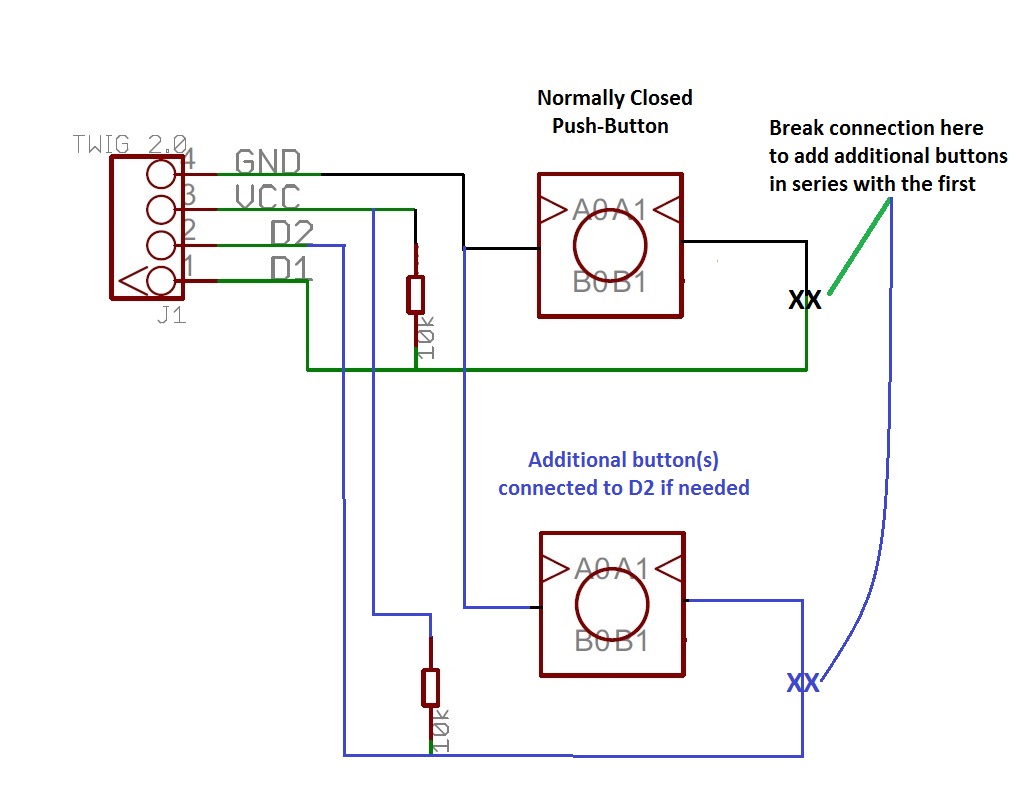
In addition to a view of the new bumper, you get a good view of the new antennae and the new camera installation on a tall piece of cardboard. You can also see the two small push-button switches that I use both as impact sensors and impact absorbing plungers. I haven’t wired them up yet as I haven’t quite figured out where I want to connect them.
Additional pictures were supposed to go here and other places throughout this article.
This forum apparently only allows people of my humble station two picture uploads. Either that, or I need to cut back on the size of the gigantic Super-Ultra-HD Quality, (three megapixels!), jpg’s I downloaded from my crummy smartphone!

The antenna upgrade:
The original antennae were two pieces of green wire from a discarded CAT-5e network cable, stripped at one end and wrapped around the bolt holding the distance sensor, (eyes), in place with the nut holding the wire in place. This was a flimsy attachment and the antennae were always getting knocked around. After the second antenna broke off, I decided it was time for an upgrade.
The new antennae are two longer pieces of wire from the same CAT-5e network cable, folded in half and twisted together using my drill. After cutting to length and placing the end of a Q-Tip over the cut ends, I glued them around the fasteners on the back of the distance sensor’s mount using high-strength contact cement. This should make a much more durable antenna and mount.
The new bumper:
After a few nasty “face-plants” into walls, chairs, and table legs while experimenting with object-avoidance software, I decided that Charlie either needed some kind of front impact-sensor/bumper, or a large stock of replacement distance sensor boards.
After thinking about, (and looking at), various options like a purchased bumper, ($$$), something made on a 3D printer that I don’t have yet, ($$$$$), or something professionally laser cut and/or created with a 3-axis milling machine, ($$$$$$$$ - #@&^**#!!!) - I knew I needed to get creative.
We had company coming over today; so last night - after my wife decided that she was out of this, that, (and everything else) - we made a late-night run to a local grocery store that’s open all night. While the wife was doing “wifey” things, I wandered around looking for whatever random thing might work as a bumper after being sufficiently modified.
I found these grill-spears and looked at them. Hmmm. . . Nice steel - long enough - shiny with a nice “crease” down its length that makes it look like a scale-model bumper. . . I was about to put it back when I saw the price: 14 rubles each, which is just about ten cents US. “Holy Smokes!” I thought. “I can’t even buy POSTAGE STAMPS for that price!” I bought three, figuring at that price, even if I screwed something up while experimenting, I could afford a few spares.
I dug out a couple of push-buttons, (that I was saving for something else, rats!), and got to work.
The GoPiGo is about 14 cm-or-so between the outside edges of the main driving wheels, so I decided to make the bumper about 16 cm long to give just a smidge of overlap on each side. I cut a 20-or-so cm piece, flattened a few cm on each end, and (tried to!) make a nice radius curve at each end to give the bumper-to-be a “finished” look, (and hide the hacked edges!)
Since I wanted the bumper to be as well mounted as possible, and I wanted to avoid any holes I might need later on for things like a line sensor, I decided to use the two last rows of holes in the hole-array on the front. They’re 8 cm apart, so I measured 4 cm from each side of a carefully, (?), marked center line and made marks there for attaching the push buttons. I also cut the handle “loop” off of the end of two spears to unfold, drill, and use as bumper mounts.
The big problem was how to attach the push-buttons to the inside of the crease that runs the length of the soon-to-be bumper. Crazy glue? Nope, that didn’t work. General purpose repair glue? No help there either. Ultimately I decided to use a (relatively) quick-setting two-part epoxy glue.
Two problems immediately came to mind:
- The push-buttons would have to be carefully balanced on their button caps while the epoxy set - and the contact area to balance on was about the thickness of a hair on each side.
- Quick-setting epoxy becomes thinner and more runny at first, (which was part of what I wanted - I wanted it to ooze and fill-in gaps), so it would provide zero support to the carefully balanced buttons while it set.
My ultimate solution was to use a bit of high-tack-strength contact cement to keep the buttons from moving around too much, and hope the epoxy had enough consistency to keep the buttons from falling over.
I ended up sticking the buttons in place with the contact cement, puddling mixed epoxy around them, carefully balancing them in a “V” shaped part of our wood-burning stove, (which gets hot - to accelerate the epoxy), and pray. I ended up checking on them about every couple of minutes or so, (and holding one uncooperative button in place by hand), while the epoxy set.
Once the buttons could hold themselves in place, I took the curved pieces I cut off to use as bumper mounts and carefully un-bent them into a modified “L” or “J” shape, giving a nicely curved right-angle bend. I added an 8 mm wide by (about) 16 mm long slot in the short side of each bend, and “carefully” (?!) marked the position of the mounting holes on the long end and drilled 2.5 mm pilot holes for the 3 mm self–tapping sheet-metal screws I was going to use to hold them in place.
They say that no battle plan survives contact with the enemy, and the same is true for pre-drilled mounting holes. Once I attached the mounts to each push-button, I discovered I had to re-mark and re-drill every stinkin’ hole! Bummer. . . .
Once the bumper was installed - and the mandatory few tweaks and bends were done - it actually looked fairly spiffy. Maybe I wasn’t going to go into the model-bumper-for-GoPiGo-robots business, but it was good looking enough that I didn’t have to hide it from my wife either.
Hopefully you enjoyed the story and we’ll see how The Bug-Mobile / Charlie does.
Jim “JR”