Ugh, my odometry is terrible

I was thinking about this trying to come up with some idea what could be going on. A couple things came to mind:

  • Have you dusted the playground and dusted Finmark’s wheels lately?
  • Perhaps try my wheelBaseRotateTest.py. With your calibrations, can you x10 360deg turns and have it end up pretty close to the original?
  • I don’t know how with the LIDAR on top, you could temporarily mount the battery closer to the two wheels, but I found Carl’s turning accuracy to improve immensely with the battery on the top plate. That is exactly why Dave has the extra layer for the LIDAR so that I could mount the battery more forward taking weight off the castor.
1 Like

Thanks for the ideas.

The wheels and the playground aren’t dusty, and I think I’m stuck with the geometry. But I’ll try the rotate test and see where it gets me. I’m traveling, so I’ll do it when I’m back home.

/K

2 Likes

Hi @KeithW, (Heavily edited post so ignore any emailed versions)

Moving back a link from the Tuning Guide, to:
navigation/Tutorials/RobotSetup/TF - ROS Wiki
I read:

“base_link” (for navigation, its important that this be placed at the rotational center of the robot)

and wondered what we are using?

The base_link of the URDF models of “Hands On ROS For Robotic Programming” is the center of a square box, and the wheels rotate about that base_link:

 <joint name="joint_left_wheel" type="continuous">
    <parent link="base_link"/>
    <child link="left_wheel"/>
    <origin xyz="0 0.30 0" rpy="0 0 0" /> 
    <axis xyz="0 1 0" />
  </joint>

I thought I followed the book’s pattern in building Dave’s URDF model, keeping the base_link at the center of the body box, and offset the wheels 20mm forward of the center of the box:

<joint name="joint_left_wheel" type="continuous">
    <parent link="base_link"/>
    <child link="left_wheel"/>
    <origin xyz="0.020 0.058 0.0325" rpy="0 0 0" /> 
    <axis xyz="0 1 0" />
  </joint>

Do you have your center of rotation at the base_link?

Somewhere I copied something I called keith_gpg.urdf which would seem to have your center of rotation 100mm in front of the base_link:

<!-- Left Wheel JOINT base_link -->
  <joint name="joint_left_wheel" type="continuous">
    <parent link="base_link"/>
    <child link="left_wheel"/>
    <origin xyz="0.1 0.15 0.0125" rpy="0 0 0" /> 
    <axis xyz="0 1 0"/>
  </joint>

Apparently it is important that the wheel link x value be 0, so I need to change my base_link visual box, the castor, the distance sensor joint, and the joint_ydlidar to put everything relative to the virtual axle between the wheels.

What I’m rebuilding my URDF with:

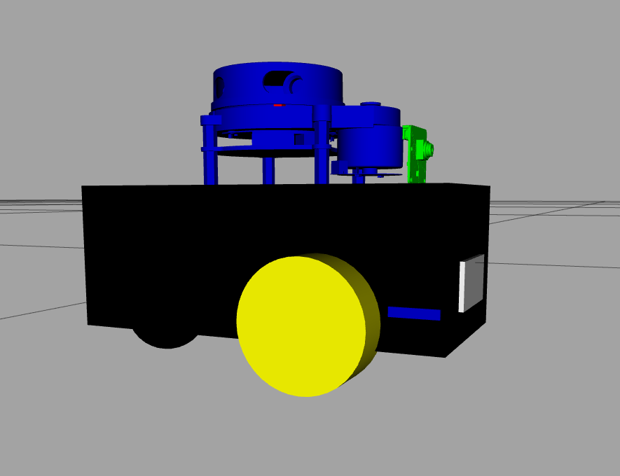
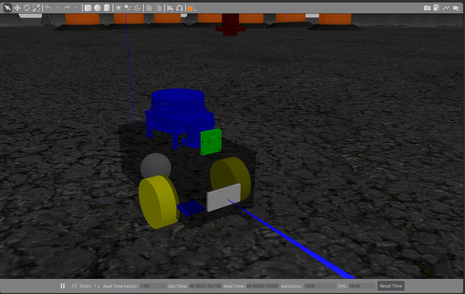
<!-- GoPiGo3 as 216mm long,  103mm wide, 4mm thick plates (blue) -->
<!--   with a 3/4 inch castor holding the chassis level (blue) -->
<!--   with (effective) 66.77mm dia 25mm wide wheels (black) spaced 106mm (Wheel base) apart -->
<!--   NOTE: The center of rotation must be at xyz="0 0 X" of the base link -->
<!--         therefore the wheel joints' x value must be 0 -->
<!--   The chassis center is 20mm back of the center of rotation (wheels) -->
<!--   DI Distance Sensor is 95mm in front of wheels -->
<!--   The LIDAR is ~22mm behind the center of rotation (wheels) -->
<!--       (A bit hard to measure after assembled.)
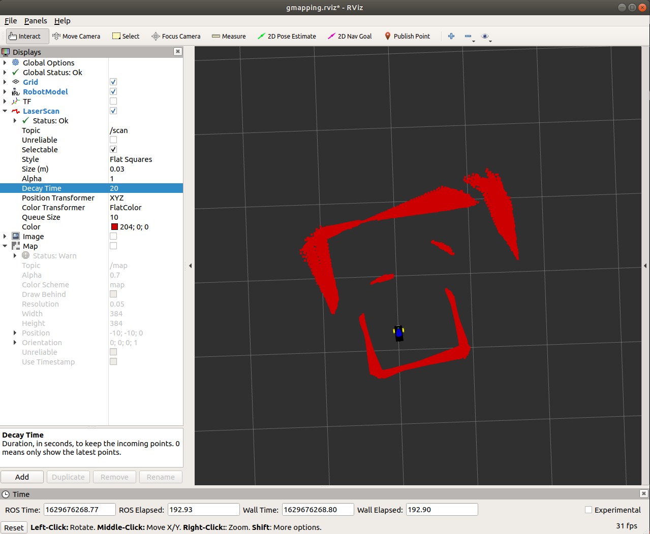
1 Like

Good catch - I’ll have to look. I’ve been meaning to update my URDF, so this provides a good reason.
/K

2 Likes

It is a real PITB! I’ve got the visual for Dave updated for the most part, only have the distance sensor to figure out why it is sticking way out. My dave.urdf is here.

2 Likes

No pressure or anything, but I’m checking twice a day to hear how you’re gettin’ on with this issue.

Finmark might have been telling you he’s in love with this bot:
FinmarkArt
She’s quite a looker, that one.

2 Likes

It’s a good thing that there isn’t an enemy submarine at the end of that scan. :wink:

I have every confidence that the two of you will get that figured out.
:+1:

2 Likes

Thanks - I was just looking at my URDF yesterday and was thinking about making it more realistic. But not sure that that matters for navigation which I think uses the URDF for the tf’s and to estimate clearance. I think it matters more for simulation to get all of the masses in the right spot.

/K

2 Likes

OK - calibration and getting the URDF a bit more correct seems to have helped.

Unlike @cyclicalobsessive, I decided to keep my URDF stylized. However I did try to get the size of the overall robot better, as well are getting wheel size and placement more correct. Also got the base_link between the wheels (at least in the xy-plane).

Here’s what it looks like in RVIZ


Note that I got rid of the distance sensor solid since it didn’t really look like the distance sensor on the GoPiGo3. I just modeled a white slab (not wanting to fool with the actual stadium shape of the real distance sensor).

The body is translucent for Gazebo.


I included a blue slab for the IMU, although I don’t actually have that implemented yet.

When I did the 360-spin in place test, note that the results aren’t nearly as bad as they were.


As I’m writing this up I may try moving the base_link to literally between the wheels (z-axis as well) to see if that helps.

/K

2 Likes

I don’t believe z-axis offset should affect xy-plane.

When you square the bot to a wall, do the scan walls appear exactly parallel and normal to the bot?
Are the scan distance values for 0,90,180, and 270 and the 0+180 and 90+270 distances accurate?
(In Dave’s case, I can see that I didn’t do a good job of getting the LIDAR 0 to line up with the bot 0.)

1 Like

Great ideas - I’ll check.
/K

1 Like

You can attach two LEGO 1x3 blocks sticking out from the front of the bot for a truly perfect square alignment.

2 Likes

Also, is your GoPiGo3 publishing Odom and tf fast enough that the scan frame is getting a good transform? I don’t know how to be certain that each scan has a tf that matches the time stamp (or does ROS interpolate frames?)

1 Like

THEORETICALLY, it shouldn’t.

However. . . .

Theoretically bees can’t fly and theoretically every publisher in ROS should have an active listener too. :wink:

I would try it as I have seen stranger things happen.

1 Like

The z location of the base_link cannot influence anything that operates only in the xy plane, but if a sensor is designed to operate with variable z, such as a distance sensor mounted on a tilt Joint, the z ref becomes essential.

Now there are some other things I can think of that might possibly cause the exhibited variance in scan distance you are seeing. One is if the GoPiGo is not level. The distance forward on a slightly front-low bot will be slightly more than the side distance when the bot has turned 90 degrees, (front and back actually). I think the variance of the cosine at small angles is relatively tiny, but since the walls are quite far, perhaps bot tilt and the z point of the tilt axis would need to be included in the URDF. And there might be some issue of vertical beam width that could cause variance, but I cannot imagine the beam width causing the consistency of distance variation in the rviz display. Also there is a variance in the actual distance measurements for the LIDAR, but I think that would be visible in the thickness of the wall line, not a variance in the wall angle.

Confirming that the 0 degree scan distance is the same as the 90 degree scan reading when the LIDAR is the same distance from each wall is a good test for any angle effect, but measuring millimeters at arms length is also fraught with difficulty for me.

The encoders output 1/2 degree precision? And the I don’t remember what my odometer turn accuracy came out to when I was doing the occupancy grid stuff, but It did not result in a perfect square path. That I do remember. It is possible that without IMU turns and odometry traverses, the scanned walls are going to spin like a bad drunk.

You mentioned location variance; Was it around 5 percent, or really gross variations?

2 Likes

Great idea - I’ll have to clear off my front deck first.

Good question - I don’t know how to check that, but will look into it.

/K

2 Likes

I think I’ve mentioned before that one of my favorite quotes is “In theory, there’s no difference between theory and practice. But in practice, there is.” So your suggestion is a fair one.

As @cyclicalobsessive points out, there are some reasons why the z-axis position might make a difference. I have noted that the lidar doesn’t pick up the far wall always. Finmark has a very slight downward slant (it had a slight upward one, but I replaced the standoffs on the back caster to fix that). I’ve checked the floor - it’s nominally level. Perhaps there is still enough difference. Or perhaps the lidar isn’t quite level. Makes me wish I had built taller walls (in theory they are tall enough :slight_smile: ).

/K

Did I? I’ll have to check.

Great idea - but I’ll also have to make sure that the walls are actually a true 90 degrees.

/K

2 Likes

In ROS (1):
rostopic hz /tf
rostopic hz /odom
rostopic hz /scan

2 Likes

/tf and /odom are about 30
/scan is about 12.65
So the /odom is easily keeping pace with the scan frame it would seem.

Started a new thread for this issue since it wasn’t directly odometry related and this thread is getting long.

/K

1 Like

Interested in what is the effect of one scan at the closest odom, and the next scan at the closest odom when the bot is spinning.
If the bot is spinning at 72 DPS say, with 30 pubs per second, then each odom is 2.4 degrees of spin on average, maybe with some +/- accuracy and some rounding for 1 degree precision of the encoders, and some jitter.

Each scans data is actually spread over 6 degrees when the bot is spinning at 77 DPS, so by the time the scan takes the 719th distance, the bot has actually rotated almost 6 degrees but the LIDAR doesn’t know that.

I’m wondering how ROS is able to use any of the data when the rotation magnitude is large. I have not looked at SLAM or localization yet, but I’m guessing the algorithms have to average out a lot of these realities.

2 Likes