Hi Team,
has anyone ever tried (and been successful) at wiring the brickpi3 to the jetson TX2 dev kit board? I’d love it if that could be doable as it’s significantly faster than the pi, more flexible for what I need to do (ai related tasks requiring GPU)… would love to hear from whomever would have experimented with this. I’ve seen a thread on the GoPiGo, but that would have been I2C I believe, and not SPI like my understanding is of brickpi3. I haven’t done deep research yet but I’m trying to understand how to do that.
I actually have it working (at least at a primary state) right now. My only issue is to figure out the pinmux on the TX2 so that the CS1 is used versus the CS0 that the PI is expecting (so they can physically be connected to the TX2 without using jumper wires where I can simply reverse the wires). I’ve seen with an analyzer and it was my problem. Is there any “Easy” way the BrickPI can be reconfigured to “listen” to chipselect 0 versus CS1?
I’m not sure about the TX2, but on the RPi, there are separate spidev “devices” for each of the SS lines. Even though electrically the “two buses” share 3 of the 4 lines, in the OS (at the SW level) they are treated as completely different buses. On the RPi they are called “spidev0.0” (bus 0 with SS 0) and “spidev0.1” (bus 0 with SS 1).
You would have to modify the BrickPi3 PCB if you wanted to change the SS pin. It’s not just a SW setting. Electrically, the SS is connected to GP7, which is pin 26. If you were to switch the SS pin, you would have to make corresponding changes in the RPi drivers. This is not recommended or supported.
If you can’t figure out how to map the SPI SS signal on the TX2 to pin 26, you could control it as a GPIO. You could set the pin to it’s active state, do the SPI transaction, and then revert the pin to it’s default state. You wouldn’t want to hold it in it’s active state any longer than necessary, but you should be able to do it fast enough. As a last resort, you could even bit-bang the entire SPI communication. It’s only 500kbps, and it should work down to at least 100kbps, so bit-banging should be very doable.
Thanks for the insightful response! Indeed they are separate devices, but i think the pin26 on the TX2 can’t be used as a GPIO. I’m waiting to get more insights from the nvidia developer forums but i really think that pin isn’t useful. How I’ve done it iw by junper wires and I might end up using that in the end if I can’t do it otherwise… not the end of the world. Not sure I’ll wire every device to the tx2 (firmware updates…, I’ll hook them up to the Pi), as I’m alone in this project and don’t have deep knowledge of all that’s required t go from A to Z from a hardware and driver point of view…
So at this point I’ve got it working on the Jetson TX2, at least working for what I’m doing so far (which is using ev3dev2’s python bindings to the ev3dev driver with the BrickPi connected to a Jetson. Not everything works and has been tested but so far the approach worked great. I’ve published the code and howto on GitHub for anyone interested in contributing or seeing how it’s built. Anyone can see the code for ev3devtx2 on GitHub. Contributions are obviously welcome! We can now do very demanding things on a Lego robot
Hello @omartin2010
I am currently trying to connect brickpi3 with zynq board (Zynqberry TE0726-03M).
When I run example programs to read Sensor data, it shows ERROR ‘No SPI Response’. Could you please share, how you made Brickpi3 work with Jetson TX2. It could be helpful for me.
Thanks in advance.
It’s been 2 years, so I don’t recall exactly but it wasn’t too difficult. In the case of the TX2, it had a SPI0 and SPI1 bus and the pins were not the same on the brickpi3 versus the TX2, so I had to invert pins in the wire as I couldn’t change how the brickpi3 was configured. I used a logic analyzer like this : Logic Analyzers from Saleae - #1 with Professional Engineers
Was actually a very useful tool for me to understand what was happening. Not sure if it will help you in your case or not…
Hi @omartin2010,
Thanks for the reply. By ‘Invert pins’ do you mean you configured signals to specific pins as expected by Brickpi3 ? I am a newbie and I did not completely understand that. Could you please explain.
These are the steps I did, can you please tell if you had done anything similar.
I currently enabled SPI0 in Zynq processor and configured the SPI pins as external. Then, I routed the signals to the GPIO pins as expected by Brickpi3.
Brickpi3 schematics I got from below website. https://drive.google.com/drive/folders/1Lc0aOtIx5IfxitarA3TCcvvx8Ebw4c0j
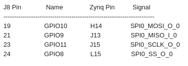
As per that I routed the SPI signals to respective GPIO pins as below.
With Logic analyzer should I check the SPI clock timing details ?
That is if this is your problem (data shows up on SPI1 when it should be on SPI0 or vice versa, again it’s been 2 years… )… iirc, I swapped only two wires on the connector, that was it. So not sure if it’s MISO and MOSI or what not, it’s been too long. But I used the analyzer to determine this was my problem. And then had to fix a few things in the driver too, it wasn’t super easy for me but I’m not a linux core compilation guru… definitely far from this!!

 )… iirc, I swapped only two wires on the connector, that was it. So not sure if it’s MISO and MOSI or what not, it’s been too long. But I used the analyzer to determine this was my problem. And then had to fix a few things in the driver too, it wasn’t super easy for me but I’m not a linux core compilation guru… definitely far from this!!