Greetings!
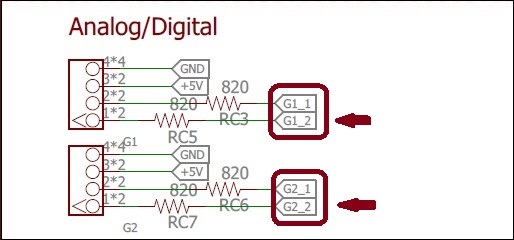
While looking at the GoPiGo-3 schematic, (looking for something else), I noticed an interesting fact about the A/D connectors - they have two signal pins.
Of course, both of the signal pins on a particular A/D connector are used for the software i2c interface, if you’re using it.
However, if you’re just using the connector as an independent A/D connector, there’s an extra signal pin you can use. And unlike the “normal” Grove A/D input, all four A/D input pins are completely independent of each other, making all of them fair game for whatever you want to do with them. (That’s assuming that you’re not using them for something else, like software i2c.)
For example, I use AD-1 on the A/D 1 connector for Charlie’s front bumper and both signal pins on A/D 2 for the Inertial Measurement Unit. I could use the other, (unused), pin on A/D 1 for a rear bumper, or as a measurement input for something.
Exactly how to get to that extra pin, I do not know. However I would not be surprised if the EasyGoPiGo library doesn’t give access to it.
Viz.:

So, if you have a project, (or a 'bot), that’s crying for an extra A/D input or two, here they are!
Enjoy!