The documentation and software for GoPiGo3 is built around the following:
Wheels are “nominally” 66.5 mm
Motors have a 1:120 gear reduction ratio
The magnetic encoders are “incremental” type (can tell direction of rotation but not absolute position)
The encoders output 6 counts per motor shaft revolution
Both the GoPiGo3 and EasyGoPiGo3 APIs read the encoder hardware in encoder counts
All GoPiGo3 and EasyGoPiGo3 APIs communicate in whole integer degrees (2 encoder counts)
For drive_inches() in the distances 21, 42, and 63 inches, my GoPiGo3 will consistently under-shoot the distance by 4%, day in and day out (around 2.5 inches in 5 feet).
My GoPiGo3 can be “calibrated” to drive with an “drive-to-drive consistent” 0.2% accuracy, by decreasing my_EasyGoPiGo3_instance.WHEEL_DIAMETER by 4%, at the start of the day (1/8 inch error after ten repetitions of driving 5 feet).
My measurements have also shown that a single calibration can achieve a “session and session-to-session consistent” 0.8% accuracy (1/2 inch error in 5 feet, with 1/8 inch drive-to-drive repeatability).
I am not complaining! On the contrary, this result has elevated my pleasure in owning a GoPiGo3 based robot . I feel a desire to learn how to use “smart” programming to create reliable robot behaviors.
Having a degree in Mechanical Engineering, and 50 years experience with motors, sensors, electronics, and software, I am aware of some of the opportunities for variance between a system design and the reality of the commercially viable product. I wish I could determine what is the mechanism that requires “fooling” the system with a 4% smaller wheel diameter than my actual measured wheels. (My wheels measure 66.5 and 66.8 mm at their largest point, and the value that achieves the best accuracy is 63.8 mm.)
Summary: The GoPiGo3 achieves very impressive drive-for-a-specified-distance accuracy.
Personally, I’m still intrigued by having a system that autocorrects the hell-approximation-induced errors so that the robot can drive straight indefinitely. (I’m referring to this post).
When you achieve such a feat, you can then map the entire world since you have a 1:1 representation of it. Unfortunately, time is the thing we (generally speaking) lack the most.
Also, thanks for sharing the code with us. That’s kind of you
I worked on sensor fusion for an autonomous cruise missile project about 25 years ago. We had a room full of Lisp machines, and developers. The four-core RPi with VideoCore 4 GPU is nearly up to the challenge, but as you point out - we still need bodies with time.
I want to understand the GoPiGo3 capabilities and limitations well, to efficiently utilize its potential. Ultimately, it will take fusing vision, ranging, odometry, (and a bunch of smarter than me kids), to escape the limitations.
I hope I don’t need “map the world” for my bot to reliably find its home, and recharge without my help every 5 to 8 hours. (The “skinny” $99 GoPiGo3 is more appealing to me than the HUGE $200 iRobot Create.
What can I say?)
At 6 increments per rotation and 120:1 gear reduction, that’s 720 increments per output rotation (0.5 degree precision). The GPG3 drivers use full (single) integer degrees. I’m not sure where you get the “even integer degrees” (± 2) from. Unless I’m missing and forgetting something, the hardware allows you to be precise to 0.5 degrees, and the drivers allow for 1 degree.
Realistically, due to gear mechanical blacklash and other small amounts of play, the precision of 0.5 degrees is greater than the mechanical accuracy.
The encoder increments per rotation (6) and gear ratio (120:1) are constants, and not subject to drift or other changes (except for an extreme mechanical or electrical failure). Since rotation is absolute in this context (one full rotation won’t be ± 5%), the only variable is how far the robot moves given a specific rotation. In this case you are effectively only dealing with wheel diameter and the wheels slipping. If you use the GPG3 on a smooth surface with the battery pack mounted on top (above the controller, leading to a better center of gravity), using mild acceleration and driving straight, there should be minimal wheel slip, so the primary variable would be wheel diameter.
In the situation you describe, you are indeed calibrating correctly. The WHEEL_DIAMETER constant can (should) be the value that’s adjusted per robot to achieve optimal distance accuracy.
Regarding the measured diameter vs. the calibrated diameter, have you considered that the wheels, with the weight of the GPG3, are being squashed down a little, effectively reducing the diameter? The default constant of 66.5mm wasn’t extensively calibrated, but seems to work about right for most applications. If it’s consistently off by about 4% (for multiple people with different robots), perhaps we should decrease it slightly.
My bot, Carl, does have additional weight on the wheels that should limit slip during drive commands to the motor starting surge.
My bot:
Total Weight 40.4oz = 2.5 lbs
Weight on rear ball caster is 12.2 oz
Weight on each wheel is around 14 oz (13.7, 14.7)
I can see a slight deflection from unweighted to full weighted, but I can’t measure it. I’m sure there is a lot going on with compression and tread effects in the contact area. The flat profile tread is also not a simple mechanism.
The place where wheel slip is extreme and visible is the rotate_deg() and orbit(,radius_cm=0) calls. I am not able to model this variance, so will need to use feedback from an external reference either minimizing ranges on a wall or matching an image from the camera.
Your method of calibrating by running 5 feet and adjusting the WHEEL_DIAMETER constant is the best way to essentially measure the effective wheel size under the weight of the robot.
After you have the diameter constant calibrated for your robot (must be done first!), you can calibrate turns by adjusting the WHEEL_BASE_WIDTH constant (default 117mm). Since the wheels make contact with a tread width greater than 0, there’s really no way to simply measure the distance between wheels, and come up with a value suitable for accurate turns. 117mm is good enough for most applications, but you might want to adjust for your robot.
In addition to the factors when driving straight, here are some of the variables that are in play when turning (left and right motors turning the same speed for the same distance, in opposite directions):
Thickness of the acrylic spacers on the motor axles. They should be right about 2mm, but due to a manufacturing misunderstanding (that has been straightened out), some existing ones range from about 1.8mm up to over 3mm. This should remain constant for your robot, but will be slightly different between robots.
The weight of the robot, causing the axles to bend slightly, or causing the play in the axles to allow the wheels to cant slightly. As weight increases, the wheels cant slightly, causing them to effectively be farther apart (where they make contact with the surface below). With a constant hardware configuration, this should be relatively constant for your robot.
Depending on the surface below, and how the tires grip (changes with weight), the tires will have a different turning “center”. The tires won’t turn at exactly the center, and not exactly the inside edge. The point they effectively turn will vary. This is due to the tread having width. Under the same conditions (including the surface it’s running on), this should also be constant for your robot.
Drag on the caster, causing slight wheel slipage. By placing the battery pack above the controller, you can bring the center of gravity forward, closer to the driving wheels, which will take weight off the caster wheel, decreasing drag. While this is of minimal importance when driving straight, it can make a big difference in accuracy and repeat-ability when turning.
There are probably other factors to consider in addition to the above.
In short, to make the robot driving and turning as accurate as possible, follow these steps:
Make the center of gravity close to the driving wheels. Start by moving the battery pack to the top of the robot.
Calibrate for the effective wheel size. Drive a specified distance (e.g. 5 feet) and adjust WHEEL_DIAMETER as necessary. Decrease the number to increase the distance.
Calibrate for the effective wheel base width. Turn a specified distance (e.g. 5 complete turns). Adjust WHEEL_BASE_WIDTH as necessary. Increase the number to increase the distance turned.
For optimum accuracy, repeat the above steps if you change the robot configuration (weight or center of gravity), or if you change the surface the robot is running on.
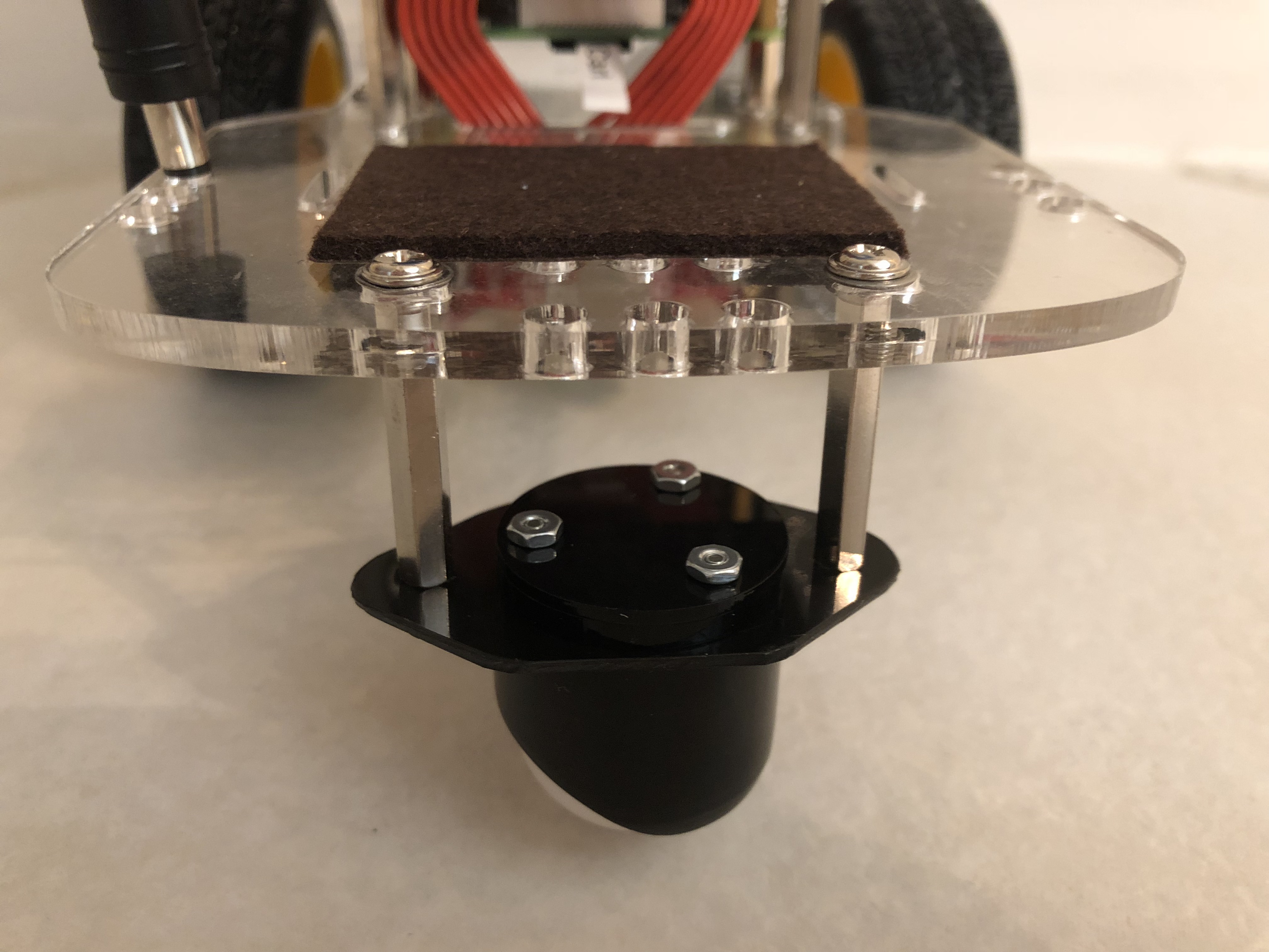
Thanks@Matt. This was the push I needed to finish the “build” of my robot Carl. I moved the battery pack inside Carl’s body, which reduced the rear castor weight from 12.2 oz down to 6.8oz, and switched out the metal ball castor with a lighter, lower friction, Pololu 1" plastic ball castor (which has 3 rollers between the mount and the ball). (With the new weight distribution, starting in reverse above 200 dps causes the castor to bounce.)
Indeed, after new wheel diameter (64.5mm) and wheel base width (114.75mm) calibrations, Carl is driving, (in his room with wood floor), four consecutive drive/return in reverse with imperceptible fwd error, and 1/8 inch reverse error in 5 feet segments, and spins 360 degrees ten times with no visible turning error.
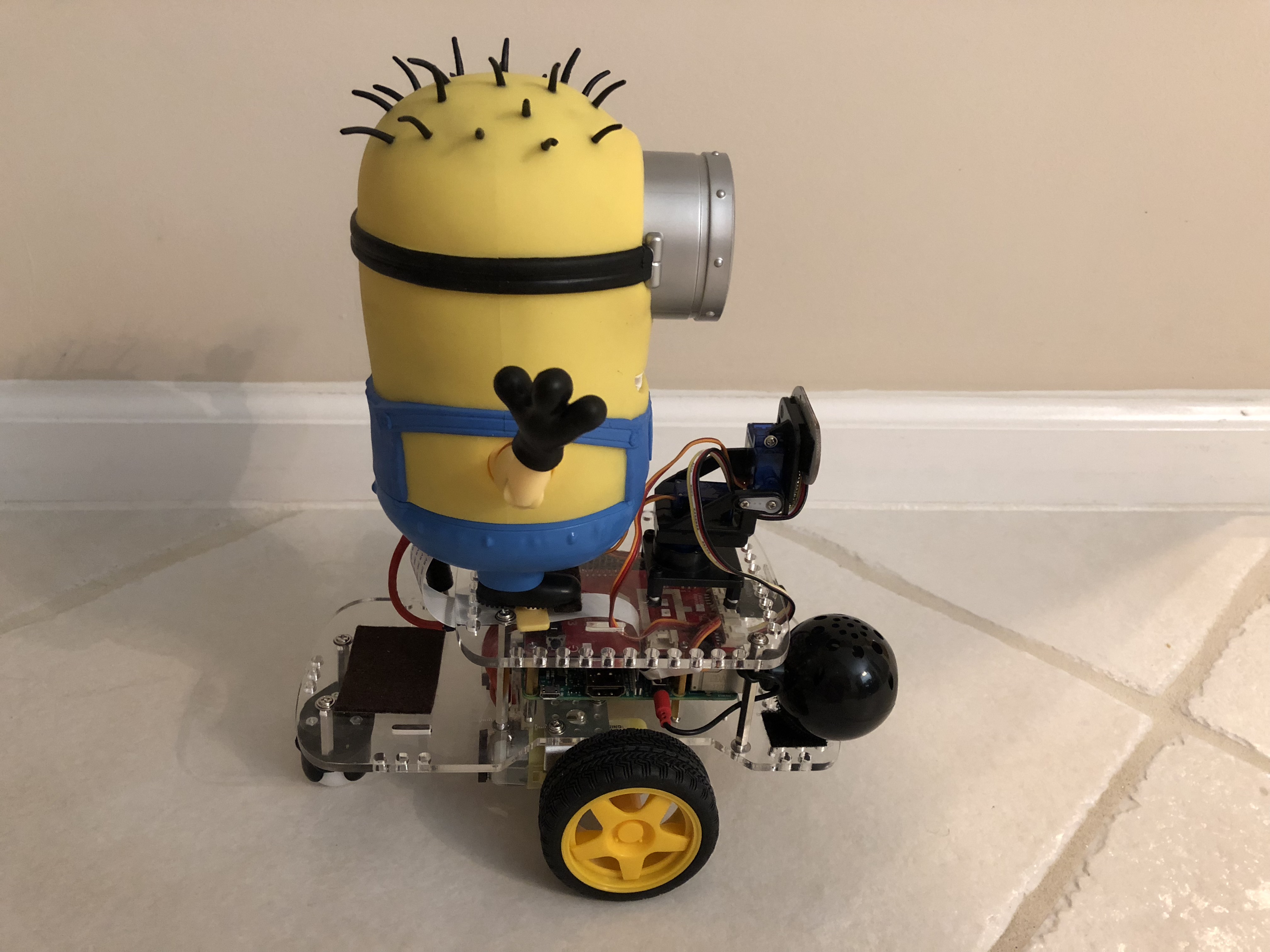
(I also mounted the Pi Camera in his eyeball ,and added a second power plug so I can recharge (with bot off) without having to constantly plug and unplug the battery pack from the GoPiGo3 board.)
Here is Carl’s new castor wheel:
And this shot shows the relative weight distribution, having the battery pack inside Carl:
This is the routine useful for manually calibrating WHEEL_BASE_WIDTH to make turn_deg() more accurate: wheelBaseRotateTest.py